Procedure
Building the River and Canal Networks
The plan for this project originally began as devising a River Network for the basin, and delineating watersheds using the methodology of CRWR-PrePro. Therefore, my initial steps consisted of the tedious process of building the river network.
|
I began by obtaining the RF3 reaches. These reaches are labelled from A - Z, and encompass every type of waterbody. Each letter represents a different reach type. Typical reachtypes in the San Jacinto-Brazos Coastal Basin are "N" = isolated stream reaches, "J" = braided stream envelopes, "O" = apparent limit reach, such as a wetland or a marsh, and "U" = the unknown reach. Because the goal is to obtain a single line network for the basin, most of the reachtypes could not be used. |
|
|
|
|
|
To obtain the usable reaches, the query tool in ArcView was used to select the "R", "S", and "T" reachtypes and convert them to a new shapefile. "R" or Regular Reaches have upstream and downstream reaches connected to them, "S" or Start Reaches are headwater reaches with no reaches above it and one or two reaches downstream, and "T" or Terminal Reaches are reaches downstream of which there are no other reaches. Now the river network is entirely single line features. Single line features must then be added to account for locations of lakes, braided streams, and other hydrology that was not originally a single line. The USGS has predetermined centerline coverages which have already existing coverages of lake and braided stream centerlines. I then merged the two shapefiles together using the GeoProcessing Wizard to obtain the river network. This network is visiblely much less dense then the original network, but nfortunately, many features of the basin are now not included. |
|


The rest of
the river network must be determined manually, using Digital Raster Graphics
(DRG's) to see the actual hydrology. The DRG's are basically USGS
Topographic Maps which show the contours and layout of the basin as well as the
canals, streams, lakes, etc. Many canals or streams that were not
considered "R", "S", or "T" reaches must still be
included in the network. To determine what to add, I added the RF3
reaches and my merged network to a view, and added a TXMesh theme that is
associated withthe DRG's. Using an "AddTopo" script written by
Jona Finndis Jonsdottir and linked to a hotlink , I added the DRG's behind the
appropriate geography, and could then edit the river network theme. The
editing tools, ![]() are used to for drawing lines and
snapping. With this process I added reaches that needed to be included in
the river network.
are used to for drawing lines and
snapping. With this process I added reaches that needed to be included in
the river network.
|
|
|
|
|
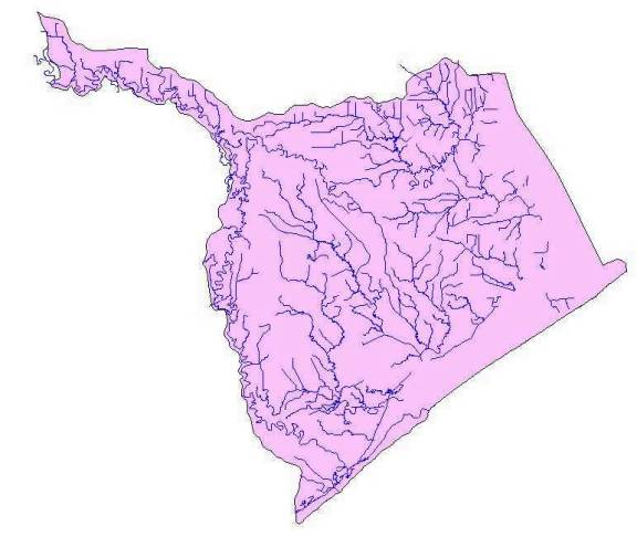
The purple lines are the RF3 reaches, and the thin blue lines are the original, unedited river network. The map behind the picture is the DRG. |
|
The purple lines are again the RF3 reaches, while the thick blue line is the edited river network. Notice in the upper right corner that two previously purple reaches are now thick blue. They have been added to the river network through editing. |


While this editing
process of manually adding reaches is very tedious and the most time-consuming
task of this project, a second equally tedious editing process also
awaits. The river network, while now single line, has two main
problems: gaps and loops. Most of the gaps occur where the
"R", "S", and "T" reaches meet the USGS
centerlines, and loops are inherent in the network. Additional editing
tools, ![]() , used for selecting and editing vertices, are
then used to stretch reaches until they intersect. Looping is eliminated
by deleting one side of the loop.
, used for selecting and editing vertices, are
then used to stretch reaches until they intersect. Looping is eliminated
by deleting one side of the loop.
|
|
|
|
|
The blue line is the RF3 reach, and the green line is the USGS centerline. Notice that they are NOT connected. |
|
This looping was inherent in the "R", "S", and "T" reaches selected from the RF3 reaches. |


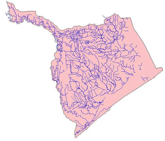
Once this editing was completed, a single line river network had been built. However, the incredibly flat nature of this region (highest elevation is 55m) has resulted in a vast canal system with intense looping as can be seen in the RF3 reaches. Because this canal system is so important to the drainage of the area, I wanted to somehow incorporate those reaches into the network. After discussion with Dr. Maidment, the method to incorporate the canal system evolved. The river network was copied to another theme, which I named the canal network. Using the editing tools previously mentioned, I added the canal reaches to the network, implicitly adding loops to the system. This canal network would then be burned in to the DEM to an arbitrary depth of 500 m while the river network would be burned in again, to a deeper arbitrary depth of 1000 m. Hopefully, this method would allow the region to drain, utilizing the canals in place.
The resulting River and Canal Network are as follows:
|
|
|
|
|
The River Network |
|
The Canal Network |


Incorporating the TMDL Segments
The next step in this project was to incorporate the TMDL Segments on the 303(d) List into the River Network. This was done using "brute force" method, of manually associating the TMDL Segment Number with the river network reaches which make up that segment.
First, I added the river network theme and the shapefile of the TMDL segments from the TNRCC to a view. Then editing the River Network Attribute Table, I added a field named Segment Number. With the TMDL segment theme active, I selected a TMDL segment. Then, with the River Network theme active, I selected the river network arcs along that TMDL segment. I then started editing the River Network Attribute Table, promoted selected arcs to the top, and entered that TMDL segment number in the Segment Number field. I repeated this process for the 11 TMDL segments. One additional segment was not included in the delineation, and that was segment 1113A. This is considered an unclassified segment, and confirmation from Bill Saunders of the TNRCC instructed to leave it out.
|
|
|
|


Once this was completed for all 11 Segments, I used the Query tool to select all River Network Reach Arcs with a Segment Number greater than zero. This effectively selected all River Network Reach Arcs which comprised a TMDL Segment. I then converted the selected arcs to a grid theme, for a grid representation of the TMDL segments.
Basin Preparation
Typical for every project, I next prepared the San Jacinto-Brazos Coastal Basin for Analysis. Rather than using CRWR-PrePro, I used ArcInfo 7.2. First I merged the three DEMs which encompassed the basin and project the result. Then, I buffered the basin outline by 10 km and clipped out the DEM to the buffered basin shape. I then filled the DEM (a time-consuming process in ArcInfo) and computed the flow direction grid and the flow accumulation grid. The following command code was used:

The following grids are the results:
|
|
|
|
|
DEM with TMDL Segments |
Flow Direction Grid |
Flow Accumulation Grid |


A procedural step of note is the lack of burning in any streams before performing any grid functions.
This is because there was a ....
Change of Plan for Watershed Delineation
While I was working on my project, Dr. Maidment and Jona Finndis Jonsdottir were independently looking at delineating watersheds with incremental drainage areas for each Reach Arc. This approach seemed ideal for my project, and the initial idea of "double burning" was abandoned. The approach now was to delineate watersheds in ArcInfo for each individual TMDL Segment. This was done using ArcInfo code which essentially created a watershed grid theme using the Flow Direction Grid and the TMDL Segments grid, then converted the watershed grid theme to a polygon theme. The code is as follows:

This procedure resulted in watersheds for each specific TMDL segment. To check the consistency of this method, I also delineated watersheds for each individual river network arc, with a grid based on a random ID number for each arc (rather than the segment number grid). The watersheds are shown below. The results are consistent, as the boundaries of each individual arc watershed coincide with the boundaries of the watersheds for the TMDL segments. With the watersheds delineated, the procedure for the scope I planned for this project is complete.

Watersheds for the TMDL Segments

Watersheds for the Individual Reach Arcs, with Watershed Boundaries for the TMDL Segments in Red
to the Project Home
to the Project Applications