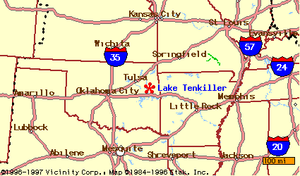
In this exercise you will acquire a fundamental familiarity of the Hydrologic Engineering Center's (HEC) new surface-water modeling program, the Hydrologic Modeling System (HMS). The beauty of the HMS lies in its graphical-user-interface, which allows you to easily set-up and execute models that incorporate processes you have learned this semester in CE 374K. This exercise will walk you through a HMS model of Lake Tenkiller, located in northeastern Oklahoma. Additionally, you will edit this model in different ways to simulate various types of hydrologic changes that may occur in the Lake Tenkiller region. For your interest, here is a map of the area:
As before, keep your eyes open while carrying out the exercise for small tasks you will need to complete.
All of the exercise will be conducted via the HMS. Unlike the Arcview exercise, this project does not require you to download vast quantities of data before you begin.
You may start the HMS on any of the PC's in LRC 3.301 by clicking
Start/Programs/hms
After a few seconds, a window similar to the following image should appear:
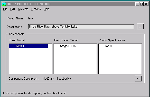
Henceforth, this image will be referred to as the Project Definition. Before we look at this window in detail, make sure you have the same image on your screen by selecting Open Project from the File menu. In the Open Project window, select tenk from the Project ID list. This will load Project tenk, which is the HMS model of Lake Tenkiller we wish to investigate.
A Project in the HMS refers to all of the data sets associated with a particular model. In this case, the Project is called tenk, which is short for Lake Tenkiller. The Description bar underneath the Project name allows you to type a detailed name for the actual short Project name. If desired, you may click on the ellipsis to the right of the Description bar, and additional space for you to type a lengthy Description will appear. For future reference, any time you see an ellipsis in a window in the HMS, it means you may access additional space for writing descriptive text.
In the Components section of the Project Definition, there are three sub-sections--the Basin Model, the Precipitation Model, and the Control Specifications. Each component represents a different element of the model. The Basin Model, for instance, contains information relevant to the physical attributes of the model, such as basin areas, river reach connectivity, or reservoir data. Likewise, the Precipitation Model holds rainfall data. Finally, the Control Specifications section contains information pertinent to the timing of the model such as when a storm occurred and what type of time interval you want to use in the model. Each of the sections is explored below individually.
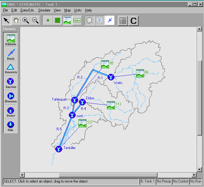
The first of the Components we will consider is the Basin Model. To view this aspect of the model, select Edit/Basin Model/Open from the menu bar on the Project Definition. A list of the available basin models will appear. In this case, your only choice is Tenk 1, so select this model by double-clicking on Tenk 1. The following image should then appear:
Before we dive headlong into the various components of this window,
let's take a minute to become more familiar with the Tenkiller region.
The ![]() icon in the
basin map represents a sub-basin within the region to be studied. The map
shows that four sub-basins are located in the study region--85, 86, 113,
and 127 (find each of these on the map). After first making sure that the
icon in the
basin map represents a sub-basin within the region to be studied. The map
shows that four sub-basins are located in the study region--85, 86, 113,
and 127 (find each of these on the map). After first making sure that the
![]() is depressed
in the Schematic, click on the icon which represents basin 86 with
the left mouse button. After this icon is highlighted, hold down the right
mouse button and choose Edit from the pop-up menu that appears.
In the upper-right-hand corner of the Subbasin Editor window that
will appear, you will find the the area of sub-basin 86. Make a note of
this value. Go ahead and look up the areas of the other sub-basins as well.
is depressed
in the Schematic, click on the icon which represents basin 86 with
the left mouse button. After this icon is highlighted, hold down the right
mouse button and choose Edit from the pop-up menu that appears.
In the upper-right-hand corner of the Subbasin Editor window that
will appear, you will find the the area of sub-basin 86. Make a note of
this value. Go ahead and look up the areas of the other sub-basins as well.
TO TURN IN: Make a table that contains the names of all of the sub-basins as well as their areas.
Now that you have noted all of the areas, follow the instructions below to capture an image of the basin map in the Schematic.
Not a bad trick, eh?? For the time being, minimize your Word window. We are going to grab other images later and place them in this same Word file so that at the end of the exercise, you only have to print out one file.
Returning to the HMS, focus your attention on the Schematic window.
This window contains a variety of buttons which you may use to assemble
and view a basin model. First, consider the top row of buttons. The ![]() button allows you to select (highlight) items in the model. You may also
use the
button allows you to select (highlight) items in the model. You may also
use the ![]() button
to drag-and-drop hydrologic elements from the left-hand-side of the window
or to move individual elements within the model. If you have a model element
highlighted, hold down the right mouse button and select Edit from
the pop-up menu to view its properties. The
button
to drag-and-drop hydrologic elements from the left-hand-side of the window
or to move individual elements within the model. If you have a model element
highlighted, hold down the right mouse button and select Edit from
the pop-up menu to view its properties. The ![]() button allows you to move (or pan) the entire model display by holding
down the left mouse button and moving the mouse. If you wish to zoom in
or out, you may do so by depressing the
button allows you to move (or pan) the entire model display by holding
down the left mouse button and moving the mouse. If you wish to zoom in
or out, you may do so by depressing the ![]() or
or ![]() button
respectively and selecting a rectangular area in the model to zoom in to
or out from by holding down the left mouse button and dragging the mouse
to draw a rectangle. Go ahead and experiment with these buttons to understand
better how each works.
button
respectively and selecting a rectangular area in the model to zoom in to
or out from by holding down the left mouse button and dragging the mouse
to draw a rectangle. Go ahead and experiment with these buttons to understand
better how each works.
The second set of icons under the menu bar allows you to choose how
the hydrologic elements are represented in the model. From left to right,
you choices are small symbol ![]() ,
large symbol
,
large symbol ![]() ,
standard icon
,
standard icon ![]() (same icons as those used on the left-hand-side of the window), or text
name
(same icons as those used on the left-hand-side of the window), or text
name ![]() . Take
a minute and select each of these buttons; notice how each button affects
the model image differently.
. Take
a minute and select each of these buttons; notice how each button affects
the model image differently.
Next, the third set of icons allows you to turn on or off the display
of the watershed boundaries ![]() ,
the river reaches
,
the river reaches ![]() ,
or flow-direction arrows on the reaches
,
or flow-direction arrows on the reaches ![]() .
As before, take some time to investigate for yourself how each of these
buttons functions. Notice that if you turn off both
.
As before, take some time to investigate for yourself how each of these
buttons functions. Notice that if you turn off both ![]() and
and ![]() while
while ![]() is turned on, you are left with a collection of icons from the elements
list. In most cases, this is how you would normally display models. For
this model, however, the watershed boundaries and the river reaches were
imported earlier as an image using a technique we will encounter in more
detail later. Keep in mind that this image has no influence on the model's
output. In the final horizontal group of buttons,
is turned on, you are left with a collection of icons from the elements
list. In most cases, this is how you would normally display models. For
this model, however, the watershed boundaries and the river reaches were
imported earlier as an image using a technique we will encounter in more
detail later. Keep in mind that this image has no influence on the model's
output. In the final horizontal group of buttons, ![]() allows you to view a chart summarizing the results from a run, while
allows you to view a chart summarizing the results from a run, while ![]() commences computations of a model. For the time being, do not use these
buttons; we'll come back to them later.
commences computations of a model. For the time being, do not use these
buttons; we'll come back to them later.
At this point, click on ![]() so that the elements in the model are displayed as they are along the left
side of the window. When creating a Schematic in the HMS, you may
choose from seven elements:
so that the elements in the model are displayed as they are along the left
side of the window. When creating a Schematic in the HMS, you may
choose from seven elements:
As needed, you may drag-and-drop elements into the model area. Go ahead
and try this, but make sure you keep the elements you add away from the
elements currently in the model. Try taking a river reach and connecting
a junction to each end. To do this, grab one ![]() and two
and two ![]() 's.
Hook up one junction to one end of the reach by highlighting the junction
(use
's.
Hook up one junction to one end of the reach by highlighting the junction
(use ![]() ) and holding
down the right mouse button. When the pop-up menu appears, select Connect
Downstream. Repeat these steps appropriately to connect the stream
to the other junction. To delete the elements you have added when you are
finished, highlight all added elements (hold down the shift key to keep
adding elements) and then choose Delete Elements from the Edit
menu in the Schematic window. If you want, take some time now to
experiment with some of the other hydrologic elements.
) and holding
down the right mouse button. When the pop-up menu appears, select Connect
Downstream. Repeat these steps appropriately to connect the stream
to the other junction. To delete the elements you have added when you are
finished, highlight all added elements (hold down the shift key to keep
adding elements) and then choose Delete Elements from the Edit
menu in the Schematic window. If you want, take some time now to
experiment with some of the other hydrologic elements.
Now that you are familiar the possible hydrologic elements in a Schematic, we are now going to investigate the model itself in more detail. This model represents Lake Tenkiller and its drainage directly upstream. The region of interest includes four sub-basins (labeled 85,86,113,127 in the image). When executed, the model performs calculations in the following order:
Since an integral part of modeling a system involves understanding the modeling software, it is important that you take a minute to walk through these steps and realize what is truly happening at each step. Remember, you will gain little from a model's results if you do not grasp what the model actually does.
As the calculation steps above suggest, the primary function of a surface-water model such as the HMS involves three sets of calculations--quantifying rainfall losses into the soil, converting excess rainfall to runoff, and routing. Recall from CE 374K that we have encountered different ways to perform the number crunching in each set. For example, we have discussed both the Green-Ampt and the Soil Conservation Service methods for determining rainfall losses to infiltration. As part of creating a HMS model, the selection of the processes to be used for each calculation set is made in the Basin Model Attributes window.
To access this window, select Basin Model Attributes from the File menu in the Schematic window. The following window should appear:
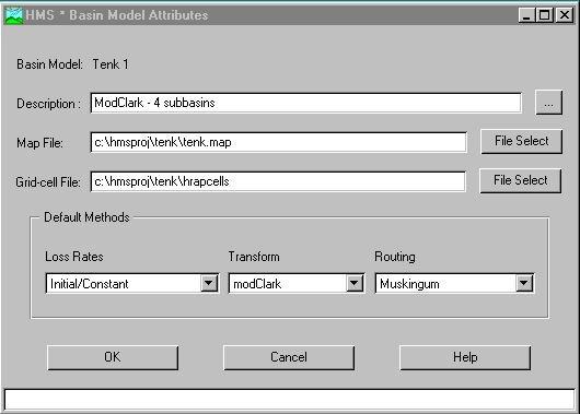
In this window, take a look at the Default Methods section.
The method on the left, Loss Rates, is where you choose the process
which calculates the rainfall losses absorbed by the ground. Click on ![]() in the Loss Rate section to see your choices. Several of these should
be familiar to you from class, especially SCS Curve No. and Green
& Ampt. In this model, Initial/Constant has been selected.
This loss relationship means that a quantity of rainfall will be absorbed
by permeable soil initially (usually about one inch), and a constant rate
will be absorbed over the time frame of the model (usually about 0.2 inches/hour).
in the Loss Rate section to see your choices. Several of these should
be familiar to you from class, especially SCS Curve No. and Green
& Ampt. In this model, Initial/Constant has been selected.
This loss relationship means that a quantity of rainfall will be absorbed
by permeable soil initially (usually about one inch), and a constant rate
will be absorbed over the time frame of the model (usually about 0.2 inches/hour).
The middle section, Transform, allows you to specify how to convert
excess rainfall to direct runoff. Again, click the ![]() to view your options, most of which you should recognize. This model employs
the modClark technique. In a nutshell, this method takes gridded
rainfall data, subtracts the losses as specified through the Loss Rates,
and converts the excess rainfall to a runoff hydrograph using a variation
of what is known as the Clark unit hydrograph. Though I am not going to
go into the details of the Clark unit hydrograph (just keep in mind that
it is similar to other unit hydrograph processes we have discussed in class),
you may go
elsewhere to learn more about how the modClark method works.
In addition, Seann Reed, a graduate student working under Dr. Maidment,
performed some of the pioneering work on converting gridded rainfall to
runoff that the HEC used when writing the HMS. You may more read about
this in an
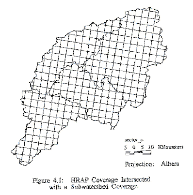
on-line copy of his Master's Report. For your interest, the following
image, taken from Seann's report, shows how the 4 km x 4 km grids were
placed on the four sub-basins in the Tenkiller region.
to view your options, most of which you should recognize. This model employs
the modClark technique. In a nutshell, this method takes gridded
rainfall data, subtracts the losses as specified through the Loss Rates,
and converts the excess rainfall to a runoff hydrograph using a variation
of what is known as the Clark unit hydrograph. Though I am not going to
go into the details of the Clark unit hydrograph (just keep in mind that
it is similar to other unit hydrograph processes we have discussed in class),
you may go
elsewhere to learn more about how the modClark method works.
In addition, Seann Reed, a graduate student working under Dr. Maidment,
performed some of the pioneering work on converting gridded rainfall to
runoff that the HEC used when writing the HMS. You may more read about
this in an
on-line copy of his Master's Report. For your interest, the following
image, taken from Seann's report, shows how the 4 km x 4 km grids were
placed on the four sub-basins in the Tenkiller region.
When using the modClark method, you must give the HMS a file which contains data specifying the locations of all of the grids in the basin. The location of this file is addressed in another window. Though it may seem that Grid-Cell File might be where this goes, that is not the case. For this exercise, ignore the Grid-Cell File bar in this window.
The final part of the Default Methods considers Routing,
which is where you specify the process for routing a hydrograph through
a river reach. Once again, click the ![]() and look over the choices. Unfortunately, while Muskingum is specified
here, it is not the routing technique used for the reaches in this model.
The version of the HMS installed for this exercise is a beta version, so
this might be a mistake. The routing techniques used in the model will
be addressed shortly.
and look over the choices. Unfortunately, while Muskingum is specified
here, it is not the routing technique used for the reaches in this model.
The version of the HMS installed for this exercise is a beta version, so
this might be a mistake. The routing techniques used in the model will
be addressed shortly.
Before we close this window, note the bar called Map File. The
file named here contains data for the graphical representation of the watershed
boundaries and river reaches, which can then be turned on and off using
![]() and
and ![]() .
This information is optional; it is here only to make the Schematic
look more attractive.
.
This information is optional; it is here only to make the Schematic
look more attractive.
At this point, close the Basin Model Attributes window by clicking on Cancel at the bottom of the window. Now that we have considered the various loss, transform, and routing techniques to use, we will look at the actual parameters associated with the chosen techniques. Choose Data-Eds. on the Schematic window menu bar. Your choices should be
Select Loss Rate and then Initial/Constant first. The following window should appear:
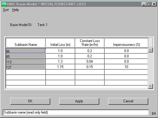
Note that while the Initial/Constant Loss Rate method was specified via another menu, it is in this table that the method parameters are actually entered. Each basin requires an initial loss quantity, a constant loss rate, and a percentage of imperviousness (notice how underdeveloped this region is). After you have looked over the data, click OK. For future reference, while both OK and Apply transfer the data to the computer's short-term memory, they differ only in that OK closes the window while Apply keeps the window open.
Once you have closed the Initial/Constant Loss window, choose Data-Eds., Transform, and then modClark to view this image:
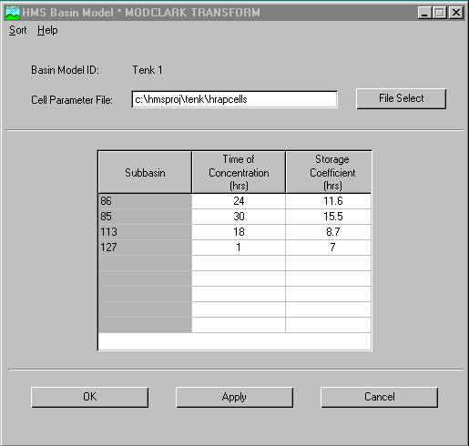
Note that the Clark unit hydrograph method requires only two parameters for each sub-basin--the time of concentration and a storage coefficient in the HMS. At this point, go ahead and close this window.
The next step involves entering the parameters for the routing process. Though the Basin Model Attributes window claimed that Muskingum routing is used, this is not the case. River reaches one through four use Modified Puls routing, which is a spin-off of the pulse function we encountered in class. From Data-Eds., select Reach Routing and then Modified Puls. This should cause the following image to appear:
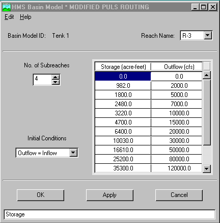
In this window, the routing data for river reach R-3 are shown. clicking
on ![]() reveals
that four of the five reaches (R-1 through R-4) in the Tenkiller system
use this routing technique. Essentially, this table of data relates storage
in the reach to outflow at the end of the reach with the Initial conditions
set as Outflow=Inflow. By altering the Number of Subreaches,
you can tell the HMS to break the river reach itself into smaller sub-components
for more accurate modeling.
reveals
that four of the five reaches (R-1 through R-4) in the Tenkiller system
use this routing technique. Essentially, this table of data relates storage
in the reach to outflow at the end of the reach with the Initial conditions
set as Outflow=Inflow. By altering the Number of Subreaches,
you can tell the HMS to break the river reach itself into smaller sub-components
for more accurate modeling.
To view the routing data for reach five, close the Modified Puls window and open the Lag window via Data-Eds./Reach Routing. Part of the window is shown below:
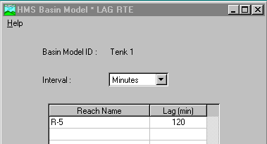
This simple routing method merely lags the output hydrograph 120 minutes behind the input hydrograph. No attenuation occurs as the water passes through this reach, which is actually Lake Tenkiller (look at the Schematic to verify this).
For your information, you do not have to go through the Data-Eds. menu to edit element properties. Editing may also be accomplished by highlighting an element, holding down the right mouse button, and choosing Edit from the pop-up menu. Since this is possible, this could also explain why Muskingum routing was chosen in the Basin Attributes window though the model actually uses other routing methods.
Before we move ahead to the precipitation data, close the Lag window and open Subbasin Area/Base Flow from Data-Eds., which should look like this:
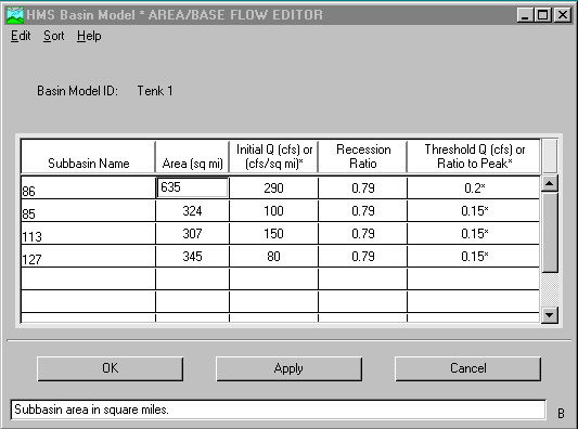
In this part of the HMS, you supply information such as basin areas and initial base flows in the system. The recession ratio and threshold Q/ratio to peak values are used by the HMS to separate baseflow from direct runoff. When you are finishing with this window, close it. In addition, you should also close the Schematic window by selecting Close from the File menu.
Whewwww!! Got all that?? While you're catching your breath, take some time to review any parts of the model that have confused you. Before we move on, you should have a fundamental understanding of what the entered data represents as well as how the HMS uses this data.
Having established the physical aspects of the model, we will now address the rainfall data. As mentioned earlier, the modClark method uses gridded rainfall information. To get this data to the HMS, go back to the Project Definition and double-click Stage3-HRAP. Consider the following image:
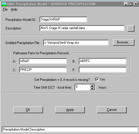
The Model ID and Description bars are locations where you may enter textual information concerning the precipitation data. The Gridded Precipitation File bar is where you tell the HMS the location of the Data Storage System (DSS) file which contains the gridded rainfall information. For each project, the HMS then creates an output DSS file which stores calculated data from all runs for a given project so that results from a previous run can be directly compared to results from a more current run. The HMS stores data in the DSS file according to the information given in the Pathnames section. F: is left blank because the HMS will place the name of the run there.
Since this model uses the modClark method, completion of this window is all that needs to be done to setup the rainfall section of the model (go ahead and close the Precipitation window). For your interest, other types of rainfall data recognized by the HMS include user-specified hyetographs, user-specified gage weighting, and frequency-based hypothetical storms. The kind of rainfall data used depends most heavily on what format is available. While the gridded data is most useful since it has the highest resolution, frequently only gauged data is available. Frequency-based storms are useful in predicting what will happen during extreme events.
The final piece of the model setup involves establishing the model's time limits. Go back to the Project Definition and double-click Jan 96 from the Control Specifications column. The resulting window is shown below:
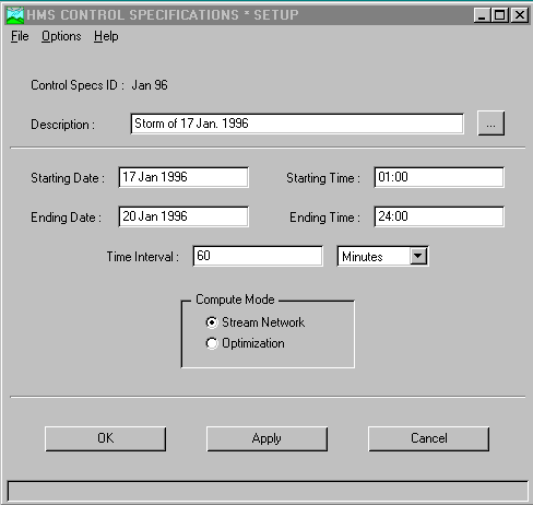
The Description of this storm indicates that we are modeling a storm that occurred on 17 Jan 1996. The model itself covers the time period of 1 am on the 17th to midnight on the 20th using a time interval of sixty minutes. Usually, the time interval in this window is the same as that of the rainfall data. When you are finished looking over this window, close it.
Finally, you have finished perusing the data involved in creating the Tenkiller model. To run the model, go the Project Definition and select Run Configuration from the Simulate menu. The following window should appear:
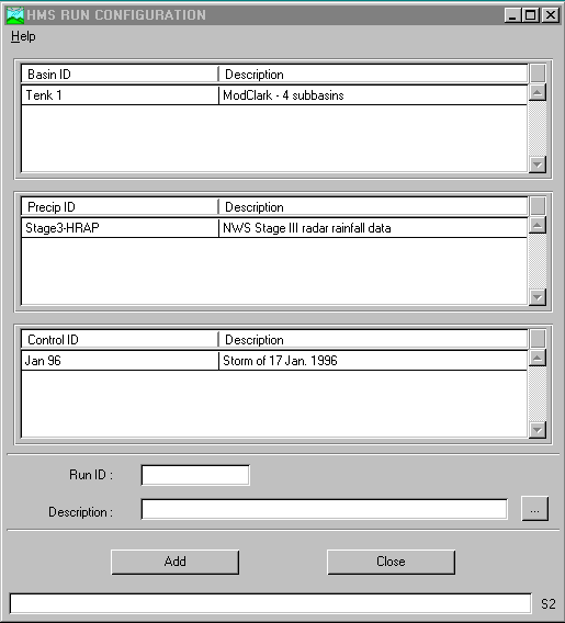
The three subsections in this window list the physical, rainfall, and timing data sets that have been created for this project. Though this model only has one data set in each section, the HMS is slick in that it allows the user to have multiple data sets available to include conveniently in different runs. Hence, if we had two different rainfall events that we wanted to model in the same Basin Model, we would use this window to select which rainfall set we wanted to include in a given run. In this case, select Tenk 1, Stage3-HRAP, and Jan 96 in the window. If you want to change the Run ID or add a Description, feel free to do so. When finished, select Add, close the Run Configuration window, go back to the Project Definition, and choose Simulation Manager from the Simulate menu. You should see an image similar to this:
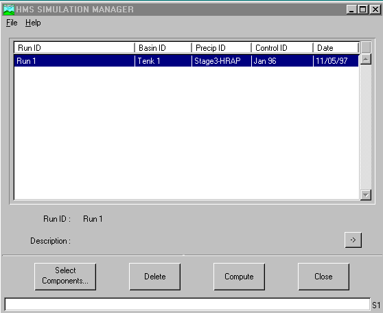
The Simulation Manager summarizes which Basin ID, Precip ID, and Control ID have been chosen for each run. In this window, Run 1 is composed of the three sets you just chose in the Run Configuration window. For the moment of truth, select Compute; if all goes well, you should see
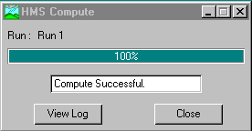
If you do not see this window, problems have arisen. When working on this exercise, I had one error which occasionally plagued me. After getting to 85% complete, sometimes I would get the message that the DSS rainfall file was unavailable. To circumvent this problem, simply close and restart the HMS. Follow the instructions from where you enter the Run Configuration section and proceed from there. That eliminated the problem 100% of the time for me. If you have any other problems, please email me (waynesboro@mail.utexas.edu).
The HMS allows you to view results in tabular or graphical form. To
view a global results table, go to the Project Definition and double-click
Tenk 1. From the window which appears (the Schematic window),
go to View and choose ![]() .
In addition to viewing global results, you may also view results for each
element within the model. To do this, choose
.
In addition to viewing global results, you may also view results for each
element within the model. To do this, choose ![]() in the Schematic window, select an element in the model (R-1 for
example) with the left mouse button, hold down the right mouse button,
and choose View Results from the pop-up menu which appears. Pick
from Graph, Summary Table, and Time-series Table.
If you view the Graph for R-1, you should see the following:
in the Schematic window, select an element in the model (R-1 for
example) with the left mouse button, hold down the right mouse button,
and choose View Results from the pop-up menu which appears. Pick
from Graph, Summary Table, and Time-series Table.
If you view the Graph for R-1, you should see the following:
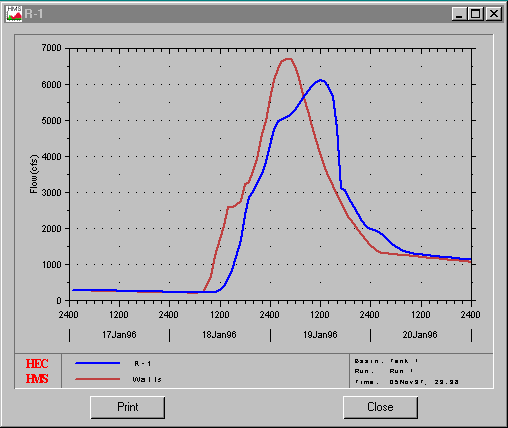
The red hydrograph is the flow data at junction Watts while the blue curve is the flow data at the downstream end of river reach R-1. Notice that the blue curve is lagged behind the red curve and slightly attenuated. You should also note that the peak outflow was about 6000 cfs around noon on 19 Jan.
TO TURN IN: Retrieve a graph of the results for river reach R-5. Capture this graph using the technique used to grab the basin map earlier and place it in the same Word file which contains your basin map. Compare the peak flow and time of this peak to those from river reach R-1. Comment on the results. Why is there no attenuation between the blue and red curves through river reach R-5??
Take some time to view other results in the model. You may view results for any of the elements in the model using the same technique outlined for the river reaches. You should view the results for some of the sub-basins in graphical form. Toward the top of the results window of a given sub-basin, you will be able to view the rainfall hyetograph for that sub-basin. Note that the dark blue in the hyetograph represents water which infiltrates the soil while pink represents rainfall available for runoff.
Hydrologic models are often used to model possible future scenarios for a given system. For the Tenkiller model, let's assume that over the next decade, Lake Tenkiller morphs into the hottest tourist attraction in America, and crazy quantities of people decide to move to northeastern Oklahoma. As people move into the region and develop it, the imperviousness values used previously become invalid. Edit them as follows:
| Subbain ID Number | Updated Imperviousness (%) |
| 85 | 35 |
| 86 | 20 |
| 113 | 35 |
| 127 | 50 |
A few notes as you do this: Numbers that you change will be brownish in color after you type them in. Make sure you always click OK or Apply after editing data. This alerts the HMS that changes have been made and converts values which are brownish to black. Keep in mind you are not permanently saving anything by clicking OK or Apply. In addition, to save the data from the previous run, you should rename this run something different in the Run Configuration window. Finally, if you want to toggle between the results of two different runs, keep the Simulation Manager window open and double-click on the run whose results you want to view. The results you view after that will apply to the run you just selected in the Simulation Manager.
Though you may want to save the project as you make changes, I am going to advise that you do not bother trying to do so. To make a long story short, there are several tricky aspects in saving a project that are not worth the time to discuss. Since the changes you are making to the project are so minor, do not worry about saving anything.
TO TURN IN: Again, capture the inflow/outflow hydrographs for river reach R-5. Comment on how the mass influx of people has altered the hydrographs for this reach.
As a final exercise, consider this. Let's assume that the day before this storm swept the Tenkiller area, another rainfall event occurred. To take this fact into account, two things need to be addressed. First, the baseflows will be higher. Arbitrarily, let's assume that they'll be triple the values the are now. Hence, you will have to update the base flow values appropriately. In addition, since the ground is saturated, the initial loss value will be zero in each sub-basin. Therefore, you will have to edit the model to reflect this as well. Finally, make sure that you change the imperviousness values back to their original values (zero per cent for all except for sub-basin 127, which had a value of ten per cent). Once you have edited these two aspects, rerun the model.
TO TURN IN: Once again, capture the inflow/outflow hydrographs for river reach R-5. Print out the Word docment where you have placed all of the images pertinent to this exercise. Discuss the influence of the initial loss value on the hydrographs in R-5.
Welcome to the end of what I hope gave you more of an insight of how topics we have learned in class are applied to actual systems. At this point, all you need to do is make sure you have completed the three 'turn in' assignments for this project. Go ahead and close the HMS by selecting Exit from the File menu in the Project Definition. When the HMS asks you if you want to save the project, choose Forget Changes.
Go to Dr Maidment's Home Page