
Geometric Design Lab - Lab 07
Define Superelevation Runoff using GEOPAK
Copyright © 2009 by Dr. Thomas W. Rioux
Students taking this course may print one copy of this document for their
personal class use.
Objective: Learn superelevation runoff design using
GEOPAK.
Activity: Copy the Texas Department of Transportation (TxDOT) GEOPAK Superelevation parameter files "txdot_e_uc.csv", "txdot_length_uc.csv", and "txdot_uc.sep" from ftp://ftp.ce.utexas.edu/class/rioux/GeometricDesignLab to "Z:\MicroStation" ; Start MicroStation and create a 2D design file "Z:\MicroStation\lab_07.dgn" using the seed file "Z:\MicroStation\train2d.dgn"; Start GEOPAK, set the standard GEOPAK user preferences for this class, and set the standard COGO preferences for this class; Create a GEOPAK Project named lab_07 using Job Number 07 with Subject of "Superelevation Runoff" and set Coordinate Geometry for Temporary Visualization; Store the points for the centerline; Store the horizontal circular curve by tangents; Create the centerline chain from elements; Draw the centerline chain and station the centerline chain; Place a flat vertical profile at elevation 0.0; Define the superelevation parameters; Process the cross sections; Draw the Pavement Edge Profiles; Place a landscape oriented rectangle centered around the drawings in 8.5" by 11" proportion; Place the title "Lab Assignment 07" at the top center and your name, class name, and assignment due date in the middle left; Place a fence from the rectangle and plot the drawing; Exit MicroStation; and Reboot the computer.
Background: Tangent runout is the length along a highway needed to transition between sections with normal crown and with adverse crown removed (zero cross slope) . Superelevation runoff is the length along a highway needed to accomplish the change in cross slope between a roadway section with adverse crown removed (zero cross slope) and a fully-superelevated section. The methodology often used, and recommended by AASHTO, to determine the length of superelevation runoff is based upon the relative pavement edge profile slope with respect to the centerline profile of a two-lane highway. This slope is taken as 1:200 (relative elevation change in the pavement edge profile over longitudinal distance) (1 foot of elevation change in 200 feet ) for a lane width of 12 feet and a design speed of 50 miles/hr. The 12 foot lane width should be used for all lane widths between 10 feet and 12 feet. In recognition of the fact that longer superelevation runoff length is desirable for higher speeds, AASHTO recommends values for relative pavement edge profile slope ranging from 1:128 at a design speed of 15 miles/hr to 1:286 at a design speed of 80 miles/hr. Tangent runout should be effected at the same rate used for superelevation runoff. The length needed to transition from normal crown to fully superelevated is thus tangent runout plus superelevation runoff.
Spiral curves are desirable to accomplish superelevation runoff. AASHTO suggests that the length of spiral should be the same as the length of superelevation runoff and that the end of the spiral at the tangent (TS or ST) should be located at the station where adverse crown has been removed (end of tangent runout). For curves without spirals, generally, 60 to 80 percent of superelevation runoff length is located on the tangent with the remaining 40 to 20 percent on the curve.
These concepts of superelevation runoff and tangent runout design are implemented in GEOPAK. Please see 2001 AASHTO Green Book pages 169-183.
A. Copy the Texas Department of Transportation (TxDOT) GEOPAK
Superelevation parameter files "txdot_e_uc.csv", "txdot_length_uc.csv",
and "txdot_uc.sep" from ftp://ftp.ce.utexas.edu/class/rioux/GeometricDesignLabto "
Z:\MicroStation"
.
B. Start MicroStation and create a 2D design file "Z:\MicroStation\lab_07.dgn" using the seed file "Z:\MicroStation\train2d.dgn".
C. Start GEOPAK, set the standard GEOPAK user preferences for this class, and set the standard COGO preferences for this class.
D. Create a GEOPAK Project named lab_07 using Job Number 07 with Subject of "Superelevation Runoff" and set Coordinate Geometry for Temporary Visualization.
E. Store the points for the centerline.
E.1. Store Point Number 1 at an X of 5000 and a Y of 5000.
E.2. Store Point Number 2 at a Bearing of N 90 E and a Distance of 1000 feet from Point Number 1.
E.3. Store Point Number 3 at a Bearing of S 45 E and a Distance of 1000 feet from Point Number 2.
E.4. Minimize the Coordinate Geometry dialog box. In MicroStation Window 1, choose the Fit View icon. The 3 points should be visible.
F. Store the horizontal circular curve by tangents using a Curve Name of CV1, Station set off, a Back Tangent with Point Back of 1 and PI Point of 2, Element set to Radius of 1200 feet, and an Ahead Tangent with Point Ahead of 3. Minimize the Coordinate Geometry dialog box. In MicroStation Window 1, choose the Fit View icon. The 3 points and the curve should be visible.

G. Create the centerline chain from elements with a Chain Name of CH1, Begin at 0+00, the 1st segment is Point 1, the 2nd segment is Curve CV1, and the 3rd segment is Point 3. Minimize the Coordinate Geometry dialog box. Minimize the Coordinate Geometry dialog box. In MicroStation Window 1, choose the Fit View icon. The 3 points, the curve, and the chain should be visible.

H. Draw the centerline chain and station the centerline chain.
H.1. Draw the centerline chain using the Design and Computation Manager using the Texas Department of Transportation (TxDOT) GEOPAK parameter file "Z:\MicroStation\txengd.ddb" selecting FEATURES then DRAFTING STANDARDS, then Alignments, then BL Baseline Horizontal Alignment, and finally Draw Plan & Profile for Job 07 setting Element Type to Chains, Curve Data to on, all other options to off, and Label Scale to 200 for Chain CH1.
H.2. Station the centerline chain setting Element Type to Stationing, Tick Marks to on, Tick Marks Stations to on, PC/PT/TS/CS/SC/ST Labels to on, PI Labels to on, Small Ticks to Ticks Right; Labels Right, Large Ticks to Ticks Both; Labels Right, Control Point Labels to As Per Preferences, and Label Scale to 200 for Chain CH1.
H.3. Close the Draw Plan & Profile dialog box and close the Design and Computation Manager dialog box.
H.4. In the Coordinate Geometry dialog box, choose Tools -> Clear Visualized Elements (Temporary).
H.5. Move the Curve Data so the PI is visible.
H.6. In MicroStation Window 1, choose the Fit View icon. The centerline chain and stationing should be visible.

I. Place a flat vertical profile at elevation 0.0.
I.1. Choose Applications -> ROAD -> Geometry -> Layout Profiles (VPI Based).
I.2. In the Settings dialog box, set Job Number to 07, set Operator Code to your 2 initials, and set PGL Chain to CH1. In the Location and Scales group, set Horizontal Scale to 10.000000, set Vertical Scale to 1.000000, set Reference Station to 0+00.00, set Reference Elevation to 0.000000, set X to 5000.0, set Y to 4000.0, and press the OK button.

I.3. In the Profile Generator dialog box, set Station to 0+00.00 and set Elevation to 0.00.

I.4. In the Profile Generator dialog box, press the Insert >> push button. In the VPI 1 group, set Back Grade to 0.0000 and press the Enter key and in the VPI 2 group, set Station to 19+48.37 (the POT at the end of the chain) and press the Enter key. In the VPI 1 group, the Length will be set to 1948.37 and in the VPI 2 group, the Elevation will be set to 0.00.

I.5. In the Profile Generator dialog box, choose File -> Save Profile As.
I.6. In the Save Profile As dialog box, set Profile to PROF1, set Input File to j07o<your_2_initials>.inp, and press the OK push button.

I.7. In the Information dialog box stating "Profile PROF1 stored", press the OK push button. Finally, close the Profile Generator dialog box. If an Alert dialog box stating "Do you want to save your profile?" appears, press the No push button (you have already saved the profile).
J. Define the superelevation parameters.
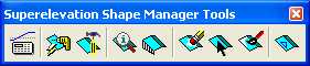
J.1. Choose Applications -> ROAD -> Cross Sections -> Superelevation Shape Manager Tools.
J.2. In the Superelevation Shape Manager Tools
dialog box, choose the Automated Superelevation icon (leftmost icon)
![]() .
.
J.3. In the Automated Superelevation dialog box, choose File -> Directories, then press the Clear All push button, and finally press the OK push button.
J.4. In the Automated Superelevation dialog box, choose File -> Preferences.
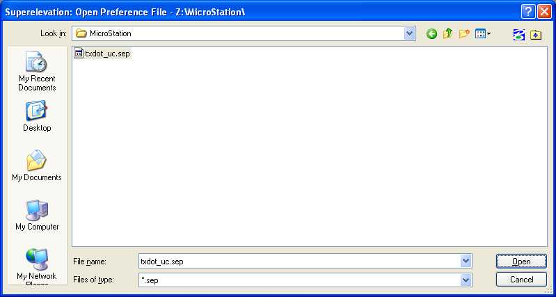
J.5. In the Superelevation Preferences dialog box, choose File -> Open.
J.6. In the Superelevation: Open Preference File dialog box, under Files of type:, select *.sep; under Look in:, choose Z:\MicroStation; in File name:, choose txdot_uc.sep, and press the Open push button.
J.7. In the Superelevation Preferences dialog box, select the e tab and set e Method to Radius Table, the Table Name: should already be set to Z:\MicroStation\txdot_e_uc.csv, set Speed Interpolation to Linear, set Radius Interpolation to Linear, and set e Rounding Increment to 0.100000.

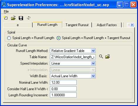
J.8. In the Superelevation Preferences dialog box, select the Runoff Length tab and select Spiral Length = Runoff Length + Tangent Runout, set Runoff Length Method to Relative Gradient Table, the Table Name should already be set to Z:\MicroStation\txdot_length_uc.csv, set Speed Interpolation to Linear, set Width Basis to Actual Lane Width, set Nominal Lane Width to 12.00, set Consider Half Lane If Width < to 0.00, and set Length Rounding Increment to 1.000000.
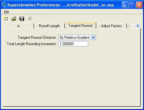
J.9. In the Superelevation Preferences dialog box, select the Tangent Runout tab and set Tangent Runout Distance to By Relative Gradient and set Total Length Rounding Increment to 1.000000.
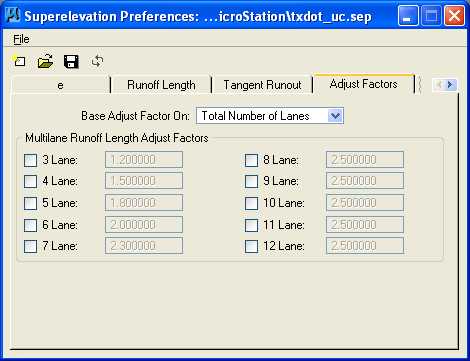
J.10. In the Superelevation Preferences dialog box, select the Adjust Factors tab and set Base Adjust Factor On to Total Number of Lanes and in the Multilane Runoff Length Adjust Factors area, deselect all.
J.11. In the Superelevation Preferences dialog box, select the Distribution tab and set Undivided Roadway Distribute Over to Tangent Runout + Runoff Length with 66.666670 % On Tangent, set Divided Roadway (High Side) Distribute Over to Tangent Runout + Runoff Length with 66.666670 % On Tangent, set Divided Roadway (Low Side) Match High Side Full Super Station, and set Station Rounding to Round Full Super Stations to Even 1.000000.

J.12. In the Superelevation Preferences dialog box, select the Rotation tab and set Transition Profile to Linear By Slope, set Outside Lane Rotation to Rotate To Match Inside Lane, and choose the left icon for Axis Of Rotation (Two Lane Undivided).

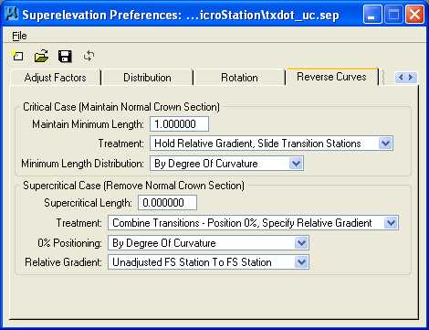
J.13. In the Superelevation Preferences dialog box, select the Reverse Curves tab and in the Critical Case (Maintain Normal Crown Section) section set Maintain Minimum Length to 1.000000, set Treatment to Hold Relative Gradient, Slide Transition Stations, and set Minimum Length Distribution to By Degree Of Curvature; and in the Supercritical Case (Remove Normal Crown Section) section set Supercritical Length to 0.000000, set Treatment to Combine Transitions - Position 0%, Specify Relative Gradient, set 0% Positioning to By Degree Of Curvature, and set Relative Gradient to Unadjusted FS Station to FS Station.
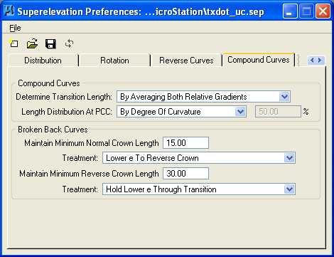
J.14. In the Superelevation Preferences dialog box, select the Compound Curves tab and in the Compound Curves section set Determine Transition Length to By Averaging Both Relative Gradients and set Distribution Length At PCC to By Degree Of Curvature; and in the Broken Back Curves section set Maintain Minimum Normal Crown Length to 15.00, set Treatment to Lower e To Reverse Crown, set Maintain Minimum Reverse Crown Length to 30.00, and set Treatment to Hold Lower e Through Transition.
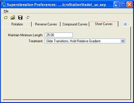
J.15. In the Superelevation Preferences dialog box, select the Short Curves tab set Maintain Minimum Length to 25.00 and set Treatment to Slide Transitions, Hold Relative Gradient.
J.16. In the Superelevation Preferences dialog box, select File -> Save.
J.17. In the Superelevation Preferences dialog box, select File -> Exit.
J.18. In the Automated Superelevation dialog box, set Job to 07, set Design Speed to 30, set Preference File to txdot_uc, set e Selection to 8% e max, set Chain to CH1, set Begin to 0+00.00, set End to 19+48.36 (NOTE: this is 0.01 less than the POT value to avoid rounding issues in GEOPAK), set Facility to Undivided, and set L Selection to all cases. Press the Left tab and set Profile to PROF1, set Tie to Offset, set Offset to 0.0000, and set Create Input File to super07.inp.

J.19. In the
Automated Superelevation dialog box, press the
Quick Entry icon
![]() .
In the Quick Entry dialog box, set Facility to Undivided, set
Lane Widths to 12.0000 feet, set Total Number of Lanes to 2,
set Nominal Percent Slope to -2.0000, and finally press the OK
push button.
.
In the Quick Entry dialog box, set Facility to Undivided, set
Lane Widths to 12.0000 feet, set Total Number of Lanes to 2,
set Nominal Percent Slope to -2.0000, and finally press the OK
push button.

J.20. In the Automated Superelevation dialog box, press the Left tab.

J.21. In the Automated Superelevation dialog box, press the Right tab.

J.22. In the Automated Superelevation dialog box, press the Generate Superelevation Transitions push button.
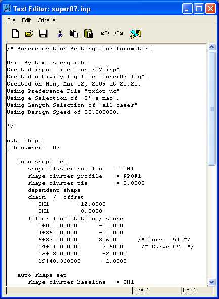
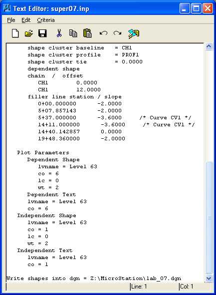
J.23. In the Text Editor: super07.inp dialog box, review the Superelevation Settings and Parameters (NOTE the filler line station values and slope values), close the Text Editor: super07.inp dialog box, and close the Automated Superelevation dialog box.
K. Process the cross sections.
K.1. In the Superelevation Shape Manager Tools dialog box, choose
the Autoshape Builder icon (2nd
icon from the left)
![]() .
.
K.2. In the Superelevation Autoshape Builder dialog box, set Autoshape Input File to Z:\MicroStation\super07.inp, deselect Display Only, deselect Override Input File Level Symbology, press the Draw Superelevation Shapes push button, and close the Superelevation Autoshape Builder dialog box.

K.3. From the MicroStation dialog box, set the View Attributes for Fill to off for All views.
K.4. In MicroStation Window 1, choose the Fit View icon. The centerline chain and stationing and the superelevation shapes should be visible.

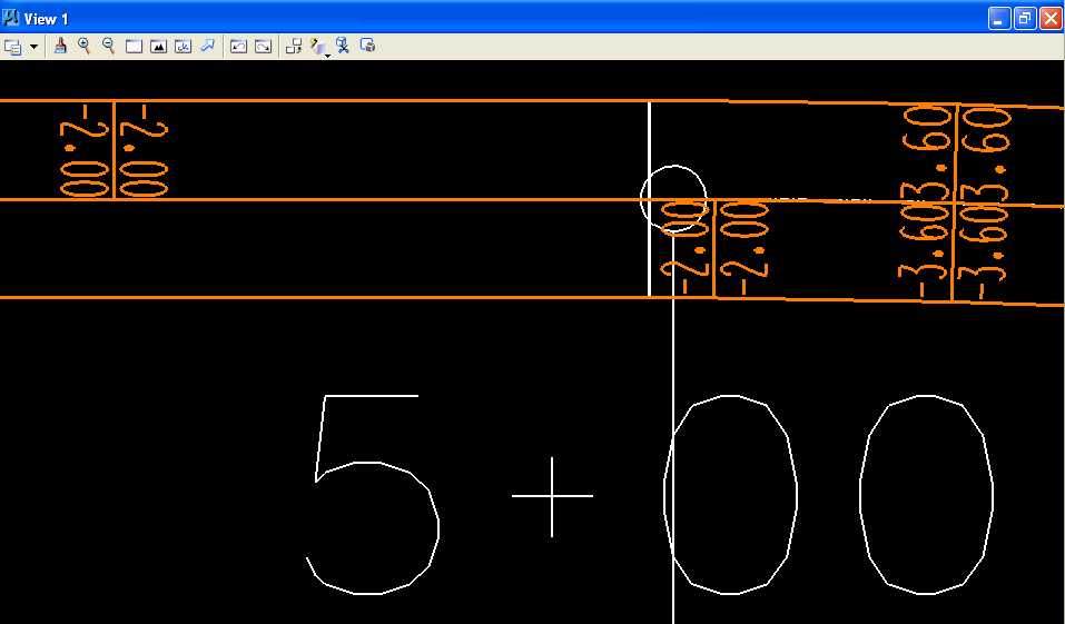
K.5. In MicroStation Window 1, choose the Zoom In icon 4 times centered on the PC of the curve. The centerline chain and stationing and the superelevation shapes should be visible.
K.6. Print the file super07.imp using a fixed-width font such as Courier New, staple the printout behind your plot, and turn in the printout with your plot.
L. Draw the Pavement Edge Profiles.
L.1. Using MicroStation, place a horizontal line starting at an X of 5000 and a Y of 4000, a length equal to the length of Chain CH1, and using level of Level 2 (level=Level 2), color of white (color=0), style of centerline (style=4), and weight of 0 (weight=0).
L.2. Label the X and Y Axis (the X Axis should be 1 foot per 1 foot and the Y Axis should be 1 percent per 50 feet) using Font=3=ENGINEERING and Text Height, Text Width, and Line Spacing of 25 feet (Hint: temporarily copy parallel the horizontal line from Step L.1 above and below the zero value 50 feet to create the 4, 3, 2, 1, -1, -2, -3, and -4 cross slopes then place a line from the 4 to the -4 line and finally copy parallel this line the required distances from the Text Editor: super07.inp dialog box from Step J.23) (Hint: use Right-Center Justification and the Intersection Snap for the Y Axis labels with the text of a zero then a blank then a minus sign then a blank ("0 - ") and an active angle of 0 and use Left-Center Justification and the Intersection Snap for the X Axis labels with the text of a minus sign then a blank then the station value ("- 0+00.00") and an active angle of 90).
L.3. Draw and label the Outside Left Pavement Edge and Inside Right Pavement Edge using level of Level 2 (level=Level 2), color of white (color=0), style of solid (style=0), and weight of 2 (weight=2) (Hint: use Intersection Snap).
M. Place a landscape oriented rectangle centered around the drawings in 8.5" by 11" proportion (2340 feet by 1800 feet) with level of Level 1 (level=Level 1), color of white (color=0), style of solid (style=0), and weight of 0 (weight=0).
N. Place the title "Lab Assignment 07" at the top center and your name, class name, and assignment due date in the middle left using a text height, text width, and text line spacing of 50 feet with font of 3 (font=ENGINEERING), justification of Center Center, level of Level 1 (level=Level 1), color of white (color=0), style of solid (style=0), and weight of 0 (weight=0).
O. Place a fence from the rectangle placed in Step M and plot the drawing using ENGR-SC2-Laser-2 and options for Fence, Monochrome, Letter, Landscape, a Scale of 250 ft / in, and Settings -> Print Attributes -> Fence boundary off and Print border on.

Define Superelevation Runoff using GEOPAK Plot
P. Exit MicroStation.
Q. Reboot the computer.
Geometric Design Lab Spring 2011 web page
Latest Update: 11 Feb 2011 03:31 PM