Geometric Design Lab - Lab 03
Areas and Dimensioning using MicroStation
Copyright © 2009 by Dr. Thomas W. Rioux
Students taking this course may print one copy of this document for their
personal class use.
Objective: Learn the concepts of points, lines, direction, distance,
traverse, bearing and distance, Northing and Easting, dimensioning, and area measurement.
Activity: Start MicroStation and create a 2D design file "Z:\MicroStation\lab_03.dgn" using the seed file "Z:\MicroStation\train2d.dgn"; In MicroStation Settings -> Design File -> Working Units, in the Modify Working Unit Settings area, in the Angles area, set Mode: to Bearing; Use MicroStation to draw the perimeter of Farmer John's land; Use MicroStation to draw the TxDOT right-of-way line on Farmer John's land; Use MicroStation to dimension each line with the bearing and distance; Use MicroStation to measure and label the area remaining in Farmer John's land and the area purchased by TxDOT; Place a landscape oriented rectangle centered around the land in 8.5" by 11" proportion (800 feet by 600 feet); Place the title "Lab Assignment 03" centered at the top and your name, class name, and assignment due date in the lower right; Place a fence from the rectangle and plot the drawing; Exit MicroStation; and Reboot the computer.
Background: A point is a location on or near the surface
of the earth. Rectangular coordinates (also called plane or Cartesian
coordinates) are used in Civil Engineering practice to define the location of points in
local surveys. Coordinates are measured linearly along a pair of orthogonal
axes that define a horizontal plane. The intersection of these axes is the
origin (0,0) of the rectangular coordinate system. From the origin, the
positive X (East) axis is to the right of the origin and the positive Y (North) axis is
upward from the origin. The Z (elevation) coordinate is measured orthogonally
to the X,Y horizontal plane.
A line is defined by a point and a direction.
A line has infinite length and extends forward and back from the line point
an infinite distance.
A direction is an angle measured from a
reference meridian (usually grid North or grid South). Azimuth from North
is the clockwise angle from the North meridian. Azimuth from South is
the clockwise angle from the South meridian. Azimuth ranges from zero to 360
degrees. Bearing is the compass direction measured: clockwise from the
North meridian in the Northeast (NE) quadrant, counterclockwise from the South meridian in
the Southeast (SE) quadrant, clockwise from the South meridian in the Southwest (SW)
quadrant, and counterclockwise from the North meridian in the Northwest (NW)
quadrant. Bearing ranges from zero to 90 degrees. Examples of
bearings: N 30 E, S 1.5 W, S 35.6 E, and N 45 W.
A distance is the length in linear units of a
line segment (straight or curved) between two points.
A traverse is a series of connected lines of
known length related to one another by known angles.
Bearing and distance is normally used to
describe relative location information; how to traverse from one point to another
point. Bearing and distance is commonly used in surveying and legal
descriptions of land to describe the perimeter of an area.
A Northing is the distance from the X
Axis to a
point while an Easting is the distance from the Y Axis to a point. A
Northing and an Easting is normally used to describe the absolute coordinate of a point.
A. Start MicroStation and create a 2D design file
"Z:\MicroStation\lab_03.dgn" using the seed file "Z:\MicroStation\train2d.dgn".
B. In MicroStation Settings -> Design File -> Angle Readout, in the Direction area, set Mode: to Bearing.
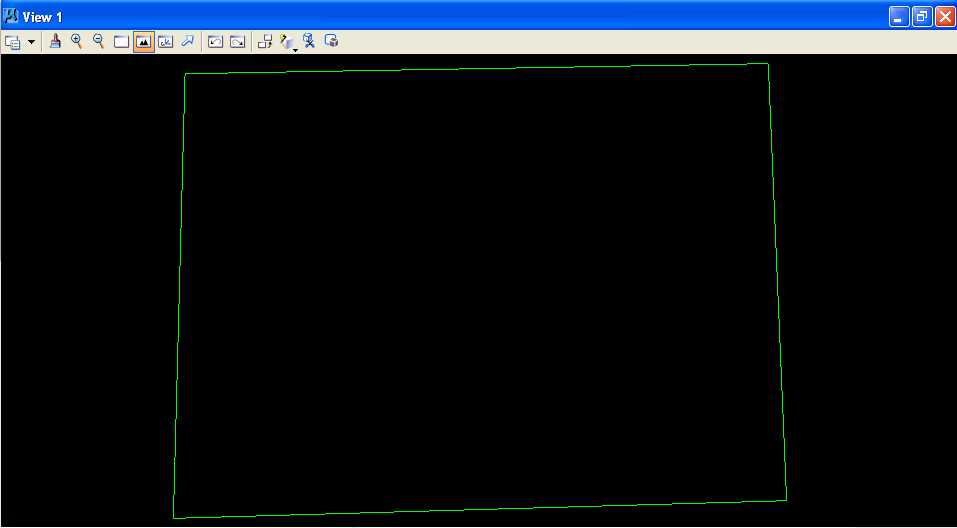
C. Use MicroStation to draw the perimeter of Farmer John's land. Farmer Johnís land starts at a point North 150 feet and East 300 feet, thence 305 feet North 1.5 degrees East, thence 400 feet North 89 degrees East, thence 300 feet South 2.4 degrees East, and finally back to the starting point. Farmer Johnís land is 124,035.7304 square feet.
C.1. Set the active level to Level 1 (level=Level 1), color to green (color=2), style to solid (style=0), and weight to 0 (weight=0).
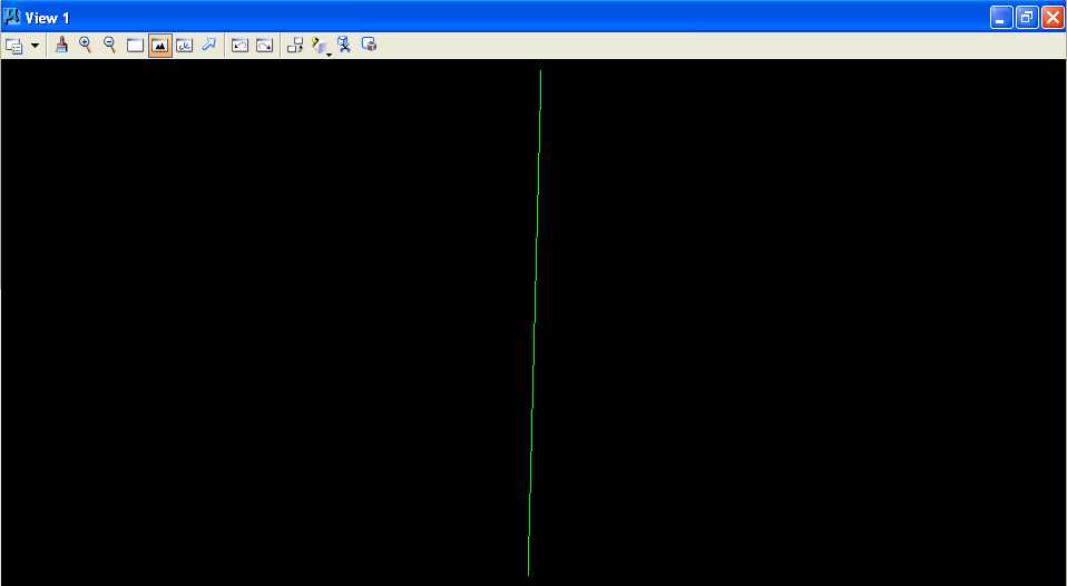
C.2. Draw a line starting at North 150 feet and East 300 feet and traversing 305 feet North 1.5 degrees East.
C.2.a. From the MicroStation Main Tool menu, select the Linear Elements palette (row 2 right icon) and open it as a tool box in the MicroStation View 1 window.
C.2.b. From the Linear Elements palette, choose the Place Line icon (2nd from left on the top row).
C.2.c. In the MicroStation Key-in field, enter "xy=300,150" plus a carriage return or the Enter key. For more information on MicroStation key-ins, in the MicroStation dialog box, choose Help -> Contents, then choose the Search tab, then enter precision, then press the List Topics push button, then double-click on Precision Input Key-ins, read the help information, and finally close the help dialog box.
C.2.d. In the MicroStation Key-in field, enter "di=305,N 1.5 E" plus a carriage return or the Enter key (be sure that you type a blank between the "N" and the "1.5" and between the "1.5" and the "E").
C.2.e. In Window 1, press the Fit View icon (the 5th icon from the left); the line should be visible.
C.2.g. Finally, press the Reset button.
C.3. Draw a line traversing 400 feet North 89 degrees East from the end of the previous line and fit View 1.
C.4. Draw a line traversing 300 feet South 2.4 degrees East from the end of the previous line and fit View 1.
C.5. Draw a line traversing from the end of the previous line to the beginning point and fit View 1.
 7
7
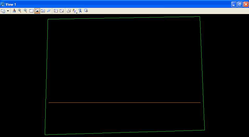
D. Use MicroStation to draw the TxDOT right-of-way line on Farmer John's land. The Texas Department of Transportation (TxDOT) wants to build a roadway where the edge of the right of way would be a due East/West line at a Northing of 235 feet and the roadway would take the southern part of Farmer Johnís land.
D.1. Set the active level to Level 2 (level=Level 2) and color to orange (color=6).
D.2. Draw a horizontal line at a Northing of 235 feet.
D.2.a. From the Linear Elements palette, choose the Place Line icon (2nd from left on the top row).
D.2.b. In the Place Line dialog box, select Length to be active and enter a value of 400 feet and select Angle to be active and enter a value of 0.
D.2.c. In the MicroStation Key-in field, enter "xy=310,235" plus a carriage return or the Enter key
D.3. Extend the horizontal line to intersect with Farmer John's land perimeter.
D.3.a. Partial Delete the line placed in Step C.2 (the first green line placed) near the intersection with the line placed in Step D.2 (the orange line) to create 2 lines and Partial Delete the line placed in Step C.4 (the third green line placed) near the intersection with the line placed in Step D.2 (the orange line) to create 2 lines.
D.3.a.1. From the MicroStation tool palette, select the Modify palette (bottom row right icon) and open it as a tool box in the MicroStation View 1 window.

D.3.a.2. From the Modify palette, press the Partial Delete
icon (2nd icon from the left)  .
.
D.3.a.3. Move the cursor over the line placed in Step C.2 (the first green line placed) just below the line placed in Step D.2 (the orange line) and press the Data button and move the cursor over the line placed in Step C.2 (the first green line placed) just above the line placed in Step D.2 (the orange line) and press the Data button (placing the first point below then placing the second point above keeps the original direction of the line in the 2 resultant lines).
D.3.a.4. Move the cursor over the line placed in Step C.4 (the third green line placed) just above the line placed in Step D.2 (the orange line) and press the Data button and move the cursor over the line placed in Step C.4 (the third green line placed) just below the line placed in Step D.2 (the orange line) and press the Data button (placing the first point above then placing the second point below keeps the original direction of the line in the 2 resultant lines).
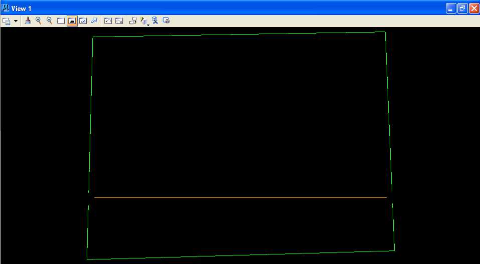
D.3.b. Extend Elements to Intersection the 2 lines created in Step D.3.a.3 to the intersection with the line placed in Step D.2 (the orange line) and Extend Elements to Intersection the 2 lines created in Step D.3.a.4 to the intersection with the line placed in Step D.2 (the orange line).
D.3.b.1. From the Modify palette, choose the Extend Elements to
Intersection icon (4th icon from the left)
 .
.
D.3.b.2. Move the cursor over the orange line and press the Data button. The orange line should be highlighted.
D.3.b.3. Move the cursor over the bottom of the 2 lines created in Step D.3.a.3 and press the Data button. Both lines should be extended to their intersection and both lines should be back to their original color.
D.3.b.4. Move the cursor over the orange line again and press the Data button. The orange line should be highlighted.
D.3.b.5. Move the cursor over the top of the 2 lines created in Step D.3.a.3 and press the Data button. Both lines should be extended to their intersection and both lines should be back to their original color.
D.3.b.6. Move the cursor over the orange line and press the Data button. The orange line should be highlighted.
D.3.b.7. Move the cursor over the bottom of the 2 lines created in Step D.3.a.4 and press the Data button. Both lines should be extended to their intersection and both lines should be back to their original color.
D.3.b.8. Move the cursor over the orange line again and press the Data button. The orange line should be highlighted.
D.3.b.9. Move the cursor over the top of the 2 lines created in Step D.3.a.4 and press the Data button. Both lines should be extended to their intersection and both lines should be back to their original color.
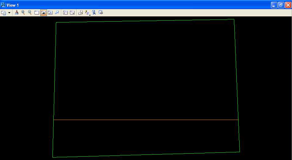
E. Use MicroStation to dimension each line with the bearing and distance.
E.1. Set the active level to Level 3 (level=Level 3) and color to yellow (color=4).
E.2. Set the text height to 10 feet, the width to 10 feet, the line spacing to 10 feet, and the font of 3 (font=ENGINEERING).
E.3. Set the dimension styles.
E.3.a. Choose Element -> Dimension Styles.
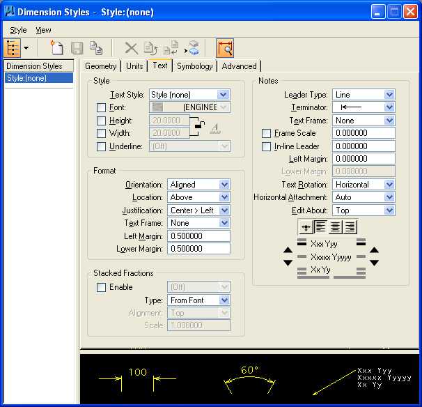
E.3.b. In the Dimension Styles dialog box, choose Text; in the Style group, set Text Style to Style (none) and deselect Font, Height, Width, and Underline; in the Format group, set Orientation to Aligned, Location to Above, Justification to Center > Left, Text Frame to None, Left Margin to 0.5, Lower Margin to 0.5; and in the Stacked Fractions group, deselect Enable.
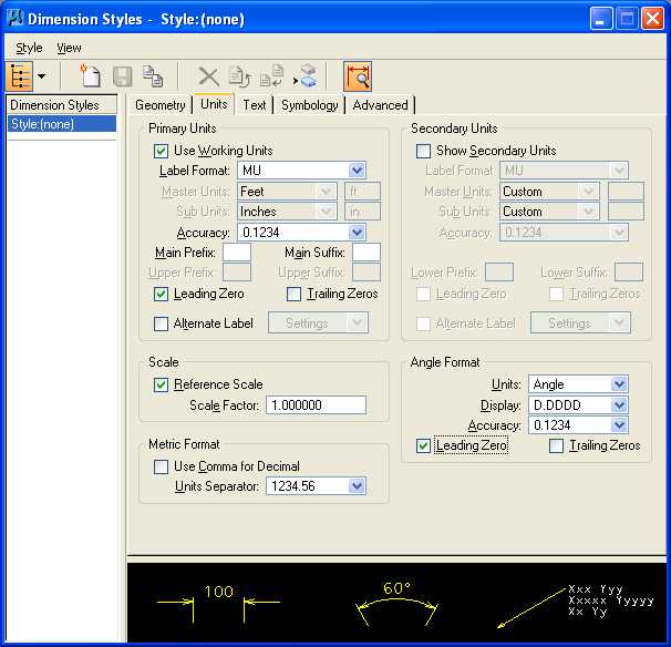
E.3.c. In the Dimension Styles dialog box, choose Units; under the Primary Units group, select Use Working Units, set Label Format to MU, set Accuracy to 0.1234, select Leading Zero, and deselect Trailing Zeros and Alternate Label; under the Secondary Units group, deselect Show Secondary Units; under the Scale group, select Reference Scale and set Scale Factor to 1.0; in the Metric Format group, deselect Use Comma for Decimal; and in the Angle Format group, set Units to Angle, set Display to D.DDDD, set Accuracy to 4 decimal places, select Leading Zero, and deselect Trailing Zeros.
E.3.d. Close the Dimension Settings dialog box.
E.4. From the MicroStation tool palette, select the Dimensioning palette (row 7 right icon) and open it as a tool box in the MicroStation View 1 window.

E.4.a. From the Dimensioning palette, choose the Dimension Element icon
(leftmost icon)  .
.
E.4.b. From the Element Dimensioning
dialog box, press the Label Line
push button
 and set Label Line to Length / Angle.
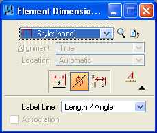
E.4.c. In the MicroStation window,
choose Settings ->
Snaps. If Keypoint
does not have a mark to its left then select Keypoint. In the
Inform Message field,
 should be displayed.
E.4.d. Repeat the following 2 instructions for each line segment:
E.4.d.1. Move the cursor to the center of the line and press the Data button.
E.4.d.2 Press the Tentative button to snap to the middle of the line and press the Data button to accept the snap.
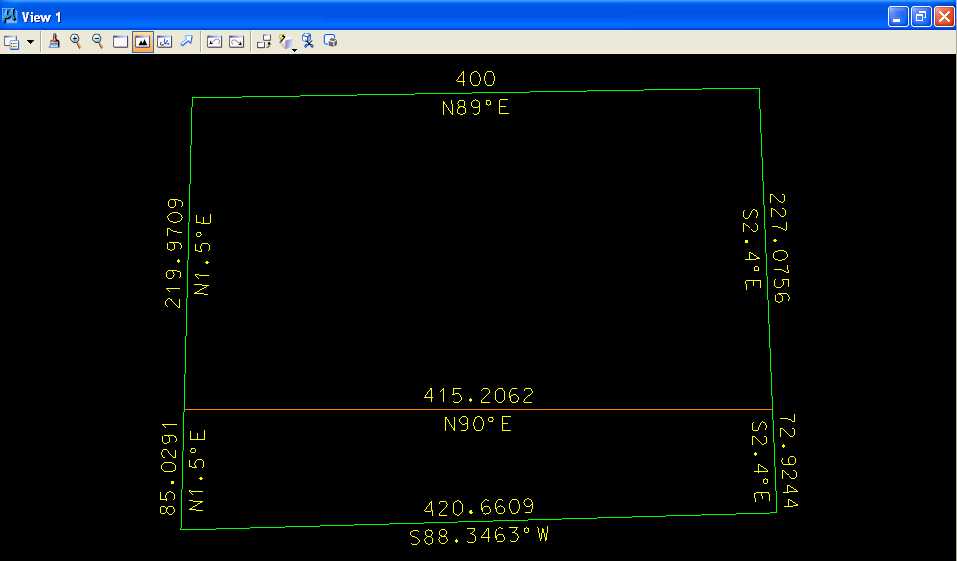
F. Use MicroStation to measure and label the area remaining in Farmer John's land and the area purchased by TxDOT.
F.1. From the MicroStation tool palette, select the Measure palette (row 7 left icon) and open it as a tool box in the MicroStation View 1 window.

F.2. From the Measure palette, choose the Measure Area icon (5th
icon from the left)  .
.
F.3. From the Measure Area dialog box, set Method to Points, set Tolerance to 1%, deselect Mass Properties and Display Centroid, set Mode to True, and set Area Unit to square ft.
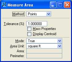
F.4. Measure the area remaining in Farmer John's land.
F.4.a. Move the cursor to the top left corner of Farmer John's land, press the Tentative button, and press the Data button anywhere to accept the tentative snap.
F.4.b. Move the cursor to the top right corner of Farmer John's land, press the Tentative button, and press the Data button anywhere to accept the tentative snap.
F.4.c. Move the cursor to the bottom right corner of Farmer John's land, press the Tentative button, and press the Data button anywhere to accept the tentative snap.
F.4.d. Move the cursor to the bottom left corner of Farmer John's land, press the Tentative button, and press the Data button anywhere to accept the tentative snap.
F.4.e. Press the Reset button and write down the value for area from the Inform Message field of the MicroStation Command Window using 4 decimal places.
F.5. Measure the area of TxDOT's land.
F.5.a. From the Measure Area dialog box, set Method to Flood, set Tolerance to 1%, deselect Mass Properties and Display Centroid, set Mode to True, set Area Unit to square ft, deselect Locate Interior Shapes and Dynamic Area, and set Max Gap to 0.0001.
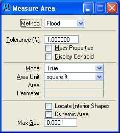
F.5.b. Move the cursor to the center of TxDOT's land, press the Data button, and press the Data button anywhere to accept the highlighted area.
F.5.c. Write down the value for area from the Inform Message field of the MicroStation Command Window using 4 decimal places.
F.6. Set the active level to Level 4 (level=Level 4), color to orange (color=6), style to solid (style=0), and weight to 0 (weight=0).
F.7. From the MicroStation tool palette, select the Text palette (row 5 right icon) and open it as a tool box in the MicroStation View 1 window.
F.8. From the Text palette, choose the Place Text icon (leftmost icon).
F.9. In the Place Text dialog box, set Method to By Origin and set Active Angle to 0.0.
F.10. In the Text Editor dialog box, enter "Area = XX,XXX.XXXX square feet" where "XX,XXX.XXXX" is the value you calculated for Farmer John's land in Step F.4.e, move the cursor to the center of Farmer John's land, and press the Data button.
F.11. In the Text Editor dialog box, enter "Area = XX,XXX.XXXX square feet" where "XX,XXX.XXXX" is the value you calculated for TxDOT's land in Step F.5.c, move the cursor to the center of TxDOT's land, and press the Data button.
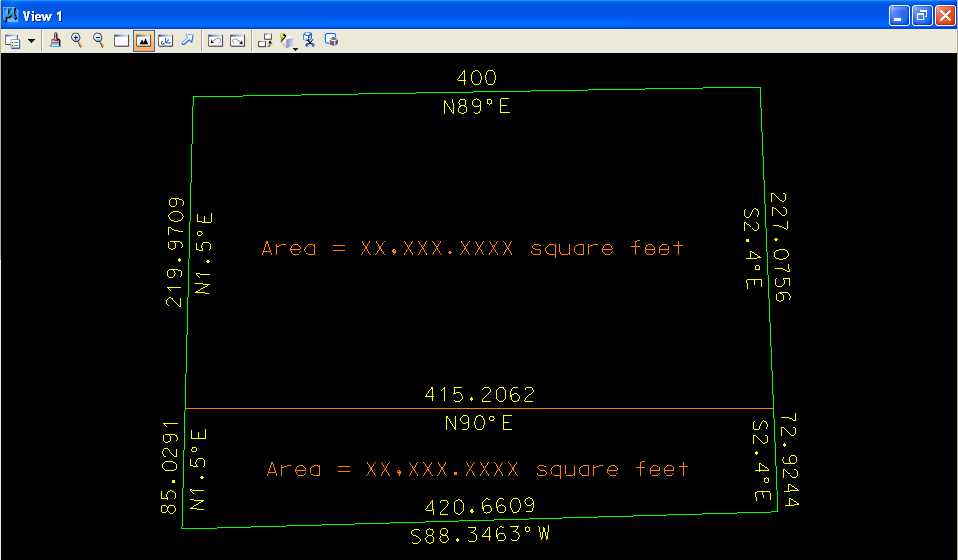
G. Place a landscape oriented rectangle centered around the land in 8.5" by 11" proportion (800 feet by 600 feet) with level of Level 1 (level=Level 1), color of white (color=0), style of solid (style=0), and weight of 0 (weight=0).
H. Place the title "Lab Assignment 03" centered at the top and your name, class name, and assignment due date in the lower right at a text height, text width, and text line spacing of 20 feet with font of 3 (font=ENGINEERING), justification of Center Center, level of Level 1 (level=Level 1), color of white (color=0), style of solid (style=0), and weight of 0 (weight=0).
I. Place a fence from the rectangle placed in Step G and plot the drawing using ENGR-SC2-Laser-2 and options for Fence, Monochrome, Letter, Landscape, a Scale of 80 ft / in, and Settings -> Print Attributes -> Fence boundary off and Print border on.
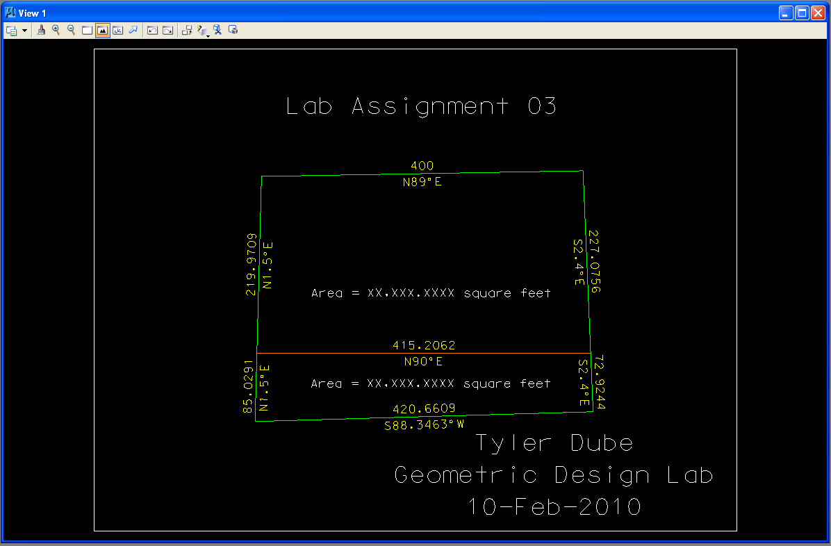
Farmer John's Land and TxDOT's Land Plot
J. Exit MicroStation.
K. Reboot the computer.
Geometric Design Lab Spring 2011 web page
Latest Update: 11 Feb 2011 02:43 PM