- Lab Assignment 05
Horizontal Circular Curve using GEOPAK
Copyright © 2005 by Dr. Thomas W. Rioux, P.E.
Updated February 1, 2008 by Ioannis Tassoulas, P.E.
Students taking this course may print one copy of this document for their personal class
use (1/2 inch margins).
Objective: Learn how to place a horizontal circular curve
using GEOPAK.
Activity: Create a GEOPAK Project, store the PI point for the horizontal circular curve, store the horizontal circular curve by tangents, create a chain, draw the chain using the Texas Department of Transportation (TxDOT) GEOPAK parameter file, and finalize the drawing for submission.
Background: A horizontal circular curve may be created in many different ways. The store curve by tangents command requires the following three data items: (1) the back tangent reference using (a) the point of curvature (PC) and the direction of the back tangent (DB), (b) the point of intersection (PI) and the DB, (c) the point back (PB) and the PI, or (d) the PB, DB, and a distance from PB to PI or PB to PC, (2) the size of the curve (e.g., radius (R), degree of curve using the arc definition, degree of curve using the cord definition, tangent length (T), length of curve (L), or a point on the curve), and (3) the ahead tangent reference using (a) the direction of the ahead tangent (DA), (b) the deflection angle (DEF), (c) the tangent distance (T), (d) the length along the curve, (e) the length of chord (LC), or the external distance (EX). Optionally, the curve may be stationed by defining a station number at the PC, PI, or point of tangency (PT). A chain is an ordered sequence of segments defining a centerline and composed of one or more points, curves, spirals, and other chains. Tangent sections between adjacent segments are automatically added if needed.
A. Start Windows Explorer and connect your LRC student volume.
B. Go at the Blackboard and then under COURSES > 08SP HIGHWAY ENGINEERING (15170) > COURSE DOCUMENTS > CE 367 LAB FILES copy the Texas Department of Transportation (TxDOT) GEOPAK Design and Computational Database ddb file: txengd.ddb to your MicroStation directory.
C. Start MicroStation and create a 2D design file "lab_05.dgn" using the seed file "train2d.dgn".
D. Start GEOPAK and set GEOPAK user preferences.
D.1. In the MicroStation dialog box on the top row, if there is no Applications item between Workspace and Window then contact the lab instructor.
D.2. In the MicroStation dialog box on the top row, if there is no Applications -> GEOPAK item then contact the lab instructor.
D.3. In the MicroStation dialog box on the top row, if there is no Applications -> GEOPAK ROAD then choose Applications -> GEOPAK -> Activate GEOPAK. A GEOPAK ROAD entry should now be in the Applications entry on the top row of the MicroStation dialog box.
D.4. Choose Applications -> GEOPAK ROAD -> User Preferences.
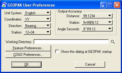
D.5. In the GEOPAK User Preferences dialog box, set Unit System to English, set Coordinates to XY, set Direction to Bearing, set Station to 12+34, under Output Accuracy set Distance to 99.1234, set Station to 9+99(9).12, set Angle Seconds to 9^9'9.12, set the Working Directory to nothing (leave blank), and set Show this dialog at GEOPAK startup to off.
D.6. In the GEOPAK User Preferences dialog box, press the COGO Preferences... push button.
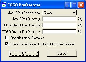
D.7. In the COGO Preferences dialog box, set Job (GPK) Open Mode to Query, set Job (GPK) Directory to nothing (leave blank), set COGO Input File Directory to nothing, set COGO Output File Directory to nothing, set Redefinition of Elements to off, set Force Redefinition Off Upon COGO Activation to on, and press the OK push button.
D.8. Finally, in the GEOPAK User Preferences dialog box, press the OK push button. This initialization operation only needs to be performed once for the rest of the semester unless otherwise instructed.
E. Create a GEOPAK Project named lab_05.
E.1. Choose Applications -> GEOPAK ROAD -> Geometry -> Coordinate Geometry.
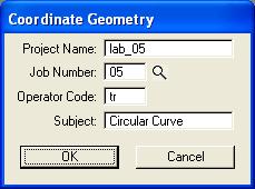
E.2. In the Coordinate Geometry dialog box, set Project Name to lab_05, set Job Number to 05, set Operator Code to your 2 initials, set Subject to Circular Curve, and press the OK push button.
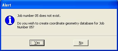
E.3. You will be prompted with an Alert dialog box asking whether you want to create job number 05. Press the OK push button.
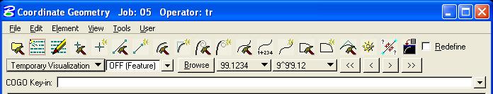
E.4. In the large Coordinate Geometry dialog box, choose Temporary Visualization.
F. Store the PI point for the horizontal circular curve.
F.1. In the Coordinate Geometry dialog box, choose Element -> Point -> Store.
F.2. In the Point Store dialog box set Point Name to 1, set X to 5000, and set Y to 5000.
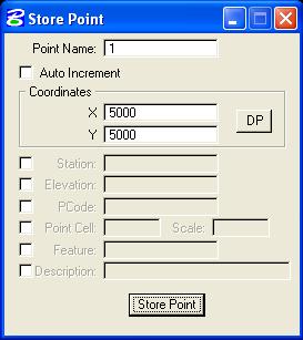
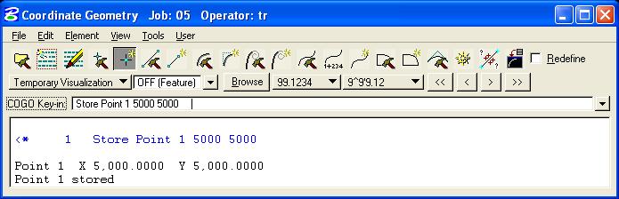
F.3. Press the Store Point push button and close the Point Store dialog box. The command issued to perform the operation (Store Point 1 5000 5000) is displayed in the upper part of the Coordinate Geometry dialog box while information about the point is listed in the lower part of the Coordinate Geometry dialog box.
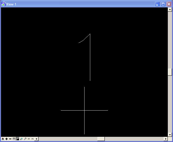
F.4. In MicroStation Window 1, choose the Fit View icon. The point should be visible (the "+" symbol is very large at this time) (this symbology is on Level 1). The "+" symbol is centered at location 5000,5000 and the "1" is the point number.
G. Store the horizontal circular curve by tangents.
G.1. In the Coordinate Geometry dialog box, choose Element -> Curve -> Store -> By Tangents.
G.2. In the Store Curve By Tangents dialog box, set Curve name to CV1, set Station to on, and set Station PI to 7+87.7326.
G.3. In the Store Curve By Tangents dialog box, in
the Back Tangent group, press the icon at the top and choose the
2nd icon from the top
 ; PI (Point of Intersection) and DB (Direction Back) are displayed
below the icon, set PI to 1, and set DB to N 90 E (there
is a space between "N" and "90" and a space between "90" and
"E").
; PI (Point of Intersection) and DB (Direction Back) are displayed
below the icon, set PI to 1, and set DB to N 90 E (there
is a space between "N" and "90" and a space between "90" and
"E").
G.4. In the Store Curve By Tangents dialog box, in the Element group, select Radius and set Radius to 1000.
G.5. In the Store Curve By Tangents dialog box, in
the Ahead Tangent group, press the icon at the top and choose
the top icon
 ; Direction Ahead (DA) is displayed below the icon, and set Direction
Ahead (DA) to S 38 E (there is a space between "S" and "38"
and a space between "38" and "E").
; Direction Ahead (DA) is displayed below the icon, and set Direction
Ahead (DA) to S 38 E (there is a space between "S" and "38"
and a space between "38" and "E").
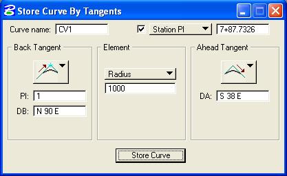
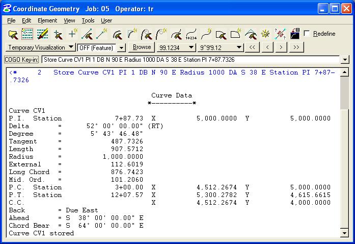
G.6. Press the Store push button and close the Store Curve by tangents dialog box. The command issued to perform the operation (Store Curve CV1 PI 1 DB N 90 E Radius 1000 DA S 38 E Station PI 7+87.7326) is displayed in the upper part of the Coordinate Geometry dialog box while information about the curve is listed in the lower part of the Coordinate Geometry dialog box.
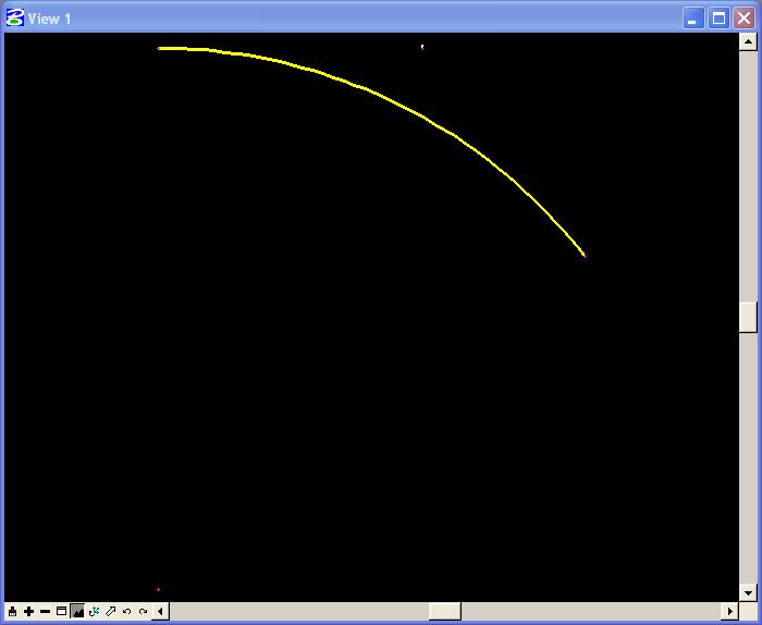
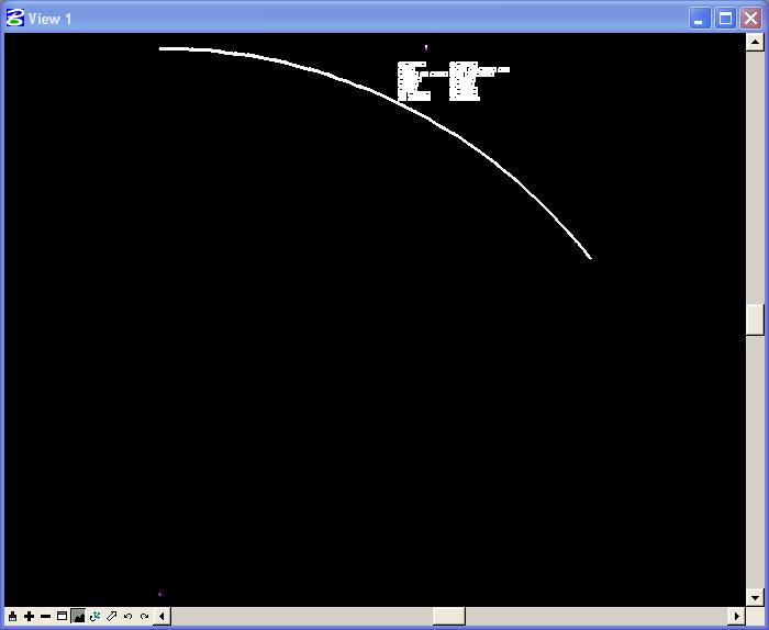
G.7. In MicroStation Window 1, choose the Fit View icon. The point and the horizontal circular curve should be visible.
H. Create a chain.
H.1. In the Coordinate Geometry dialog box, choose Element -> Chain -> Store -> From Elements.
H.2. In the Store Chain From Elements dialog box, set Chain Name to CH1 and set the option button below Chain Name to Station As Is.
H.3. In the Element Selection group, set Element Type to Curve (the curve CV1 should appear selected in the box below the Curve option button, press the < Add push button, and CUR CV1 should appear in the Element List box on the left.
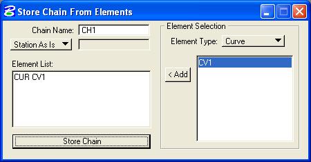
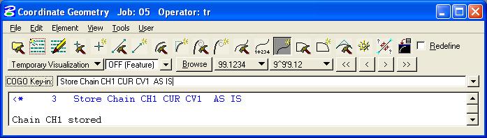
H.4. Finally press the Store Chain push button and close the Store Chain From Elements dialog box. The command issued to perform the operation (Store Chain CH1 CUR CV1 AS IS) is displayed in the upper part of the Coordinate Geometry dialog box while information about the chain is listed in the lower part of the Coordinate Geometry dialog box.
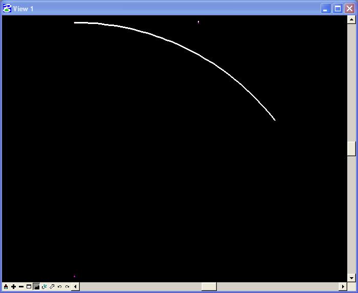
H.5. In MicroStation Window 1, choose the Fit View icon. The horizontal circular curve chain should be visible.
H.6. Minimize the Coordinate Geometry dialog box by pressing the
 icon in the upper right corner.
I. Draw the horizontal circular curve.
I.1. Choose Applications -> GEOPAK ROAD -> Design & Computation Manager.
I.2. In the Design and Computation Manager dialog box, choose File -> Open.
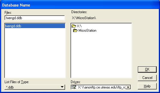
I.3. In the Database Name dialog box under Directories, make sure your "X:\MicroStation" directory is selected, then under Files, choose txengd.ddb, and finally press the OK push button.
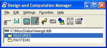
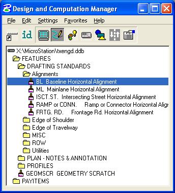
I.4. In the Design and Computation Manager dialog box, the top line should have X:\MicroStation\txengd.ddb listed followed by FEATURES and PAYITEMS.
I.5. In the Design and Computation Manager dialog box, double click on FEATURES, then double click on DRAFTING STANDARDS, then double click on Alignments, and then select BL Baseline Horizontal Alignment.
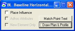
I.6. In the BL Baseline Horizontal Alignment dialog box, press the Draw Plan & Profile push button.
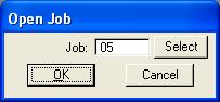
I.7. In the Open Job dialog box, set Job to 05 and press the OK push button.
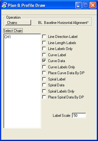
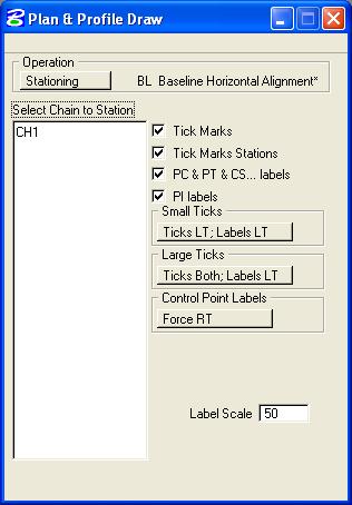
I.8. In the Plan & Profile Draw dialog box, set Operation to Chains, set Curve Data to on, and set all other options to off. Finally, set Label Scale to 50 and in the Select Chain group select CH1 (press CH1 only once; the chain should be drawn immediately).
I.9. In MicroStation Window 1, choose the Fit View icon. The horizontal circular curve chain and curve data should be visible.
I.10. In the MicroStation window, choose Window -> Design and Computation Manager (this action should bring the Design and Computation Manager window to the front).
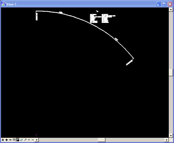
I.11. In the Plan & Profile Draw dialog box, set Operation to Stationing, set Tick Marks to on, set Tick Marks Stations to on, set PC & PT & CS... labels to on, set PI labels to on, set Small Ticks to Ticks LT; Labels LT, set Large Ticks to Ticks Both; Labels LT, set Control Point Labels to Force RT, and set Label Scale to 50. In the Select Chain to Station group, select CH1 (press CH1 only once; the labeling should be drawn immediately). Close the Plan & Profile Draw dialog box and close the Design and Computation Manager dialog box.
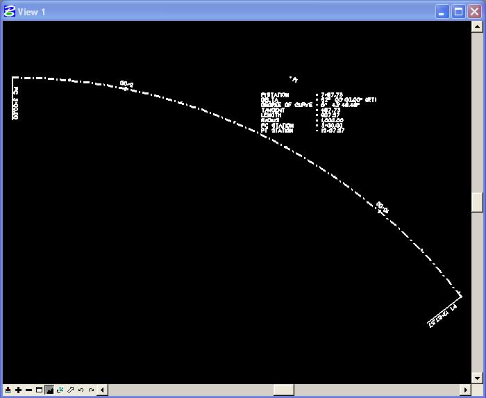
I.12. In MicroStation Window 1, choose the Fit View icon. The horizontal circular curve chain, curve data, and stationing should be visible.
I.13. In the MicroStation window, choose Window -> Coordinate Geometry.
I.14. In the Coordinate Geometry dialog box, choose Tools -> Clear Visualized Elements (Temporary).
I.15. Close the Plan & Profile Draw dialog box and close the Design and Computation Manager dialog box.
I.16. In MicroStation Window 1, choose the Fit View icon. The horizontal circular curve chain, curve data, and stationing should be visible without the temporary visualization elements.
I.17. In the Coordinate Geometry dialog box, choose File -> Exit.
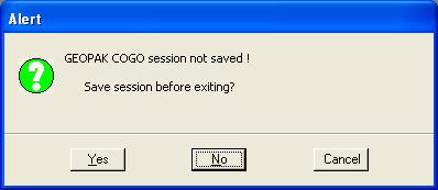
I.18. An Alert dialog box should appear stating that the GEOPAK COGO session was not saved and asking whether to Save session before exiting? Press the No push button. The GEOPAK COGO data has already been stored automatically; this is whether you want to save the command history.
J. Place a landscape oriented rectangle centered around the horizontal curve in 8.5" by 11" proportion (850 feet by 650 feet) with level of Level 1 (level=Level 1), color of white (color=0), style of solid (style=0), and weight of 0 (weight=0).
K. Place the title "Lab Assignment 05" at the top center and your name, class name, and assignment due date in the bottom left at a text height, text width, and text line spacing of 25 feet with font of 3 (font=ENGINEERING), justification of Center Center, level of Level 1 (level=Level 1), color of white (color=0), level of Level 1 (level=Level 1), style of solid (style=0), and weight of 0 (weight=0).
L. Place a fence from the rectangle placed in Step J and plot the drawing using options for fence, Monochrome, printer.plt, letter, landscape, a scale of 100 ft / in, fence boundary off, and plot border on.
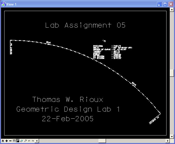
Horizontal Circular Curve using GEOPAK Plot
M. Exit MicroStation.
Lab Assignment 05 is due .
Latest Update: 01 Feb 2008 05:14 PM