- Lab Assignment 01
Introduction to MicroStation
Copyright © 2005 by Dr. Thomas W. Rioux, P.E.
Updated January 14, 2008 by Ioannis Tassoulas, P.E.
Students taking this course may print one copy of this document for their personal class
use (1/2 inch margins).
Assignment: Please send an e-mail to Ioannis Tassoulas at jtassoulas@sbcglobal.net or jtass@yahoo.com with your e-mail address.
Objective: Learn the basics of MicroStation required to operate GEOPAK.
Activity: Learn the basics of MicroStation by creating a 2D training seed file and reviewing MicroStation commands, menus, and dialog boxes. The 2D training seed file will be used for most labs.
Background: MicroStation is a Computer Aided Drafting (CAD) software package. GEOPAK is an engineering software that runs using the MicroStation platform. Certain knowledge of MicroStation is required to use and operate GEOPAK.
Prerequisites: Prior to the lab please be sure that you have both accounts with CE-LRC and ENGR active. You will need the ENGR account in order to use the computers at the HP2 Lab in ECJ 3.402 and the CE-LRC account to save your Microstation and Geopak files to your STU folder. This way you will be able to have all lab files available with the others computers on the 3rd floor outside the ECJ 3.402 room. You may find more details in setting your accounts at http://www.caee.utexas.edu/itss/
In MicroStation, we will be calling the Left Button on the 3-button mouse the Data Button, the Middle Button (wheel) the Tentative Button, and the Right Button as the Reset Button.
A. Start Windows Explorer and connect your CE-LRC student directory.
A.1. From the Windows Start Menu in the lower left corner of the screen, choose Start -> All Programs -> Accessories -> Windows Explorer.
A.2. From the My Documents dialog box, expand My Computer and if you are not connected to your STU folder follow the next steps..
A.3. From the My Documents dialog box, choose Tools -> Map Network Drive.
A.4. In the Map Network Drive dialog box, set Drive: to X:.
A.5 Follow steps 1-6 described at http://www.caee.utexas.edu/itss/map2kXPstu.cfm to map to STU directory. Also check the "Reconnect at logon".
B. Start MicroStation and create a 2D design file "train2d.dgn" using the seed file "seed2d.dgn".
B.1. From the Windows Start Menu in the lower left corner of the screen, choose Start -> All Programs -> MicroStation -> MicroStation.
B.2. From the MicroStation Manager dialog box, choose File -> New.
B.3. From the New dialog box in the Seed File group, choose Select.
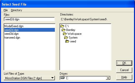
B.4. From the Select Seed File dialog box under Directories, select the device and directory for MicroStation seed files (normally "c:\Program Files\Bentley\Workspace\System\seed"); then under Files:, select seed2d.dgn; and finally press the OK push button. "c:\Program Files\Bentley\Workspace\System\seed" should now appear as the Seed File.

B.5. From the New dialog box under Directories, make sure your "x:\<first_character_of__username>\<_username>\microstation" directory is selected; under File Type, select MicroStation DGN Files (*.dgn); under Files:, enter train2d.dgn; and finally press the OK push button.
B.6. From the MicroStation Manager dialog box under Directories, make sure your "x:\<first_character_of__username>\<_username>\microstation" directory is selected; then under Files:, select train2d.dgn; in the Workspace group, set User: to untitled, set Project: to General, and set Interface: to default; and finally press the OK push button.
C. Set the MicroStation Design File Settings.
C.1. From the MicroStation dialog box, choose Settings -> AccuDraw.
C.2. In the AccuDraw Settings dialog box under the Operation tab, set Auto Load to off and close the AccuDraw Settings dialog box by pressing the "X" in the upper right corner of the dialog box.
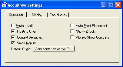
C.3. If there is an AccuDraw dialog box currently open, close the AccuDraw dialog box by pressing the "X" in the upper right corner of the dialog box.

C.4. From the MicroStation dialog box, choose Settings -> Design File...
C.5. In the DGN File Settings dialog box under Category, choose Active Angle. In the Modify Active Angle Settings area, set Active Angle to 0.0; set Angle Lock to off; and set Tolerance to 1.0.

C.6. In the DGN File Settings dialog box under Category, choose Active Scale. In the Modify Active Scale Settings area, press the 1.0 button, ensure that the lock to the right of the X Scale and Y Scale boxes is in the locked position (press the lock if it is not in the locked position); set Scale Lock to off; and set Tolerance to 1.0.
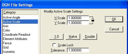
C.7. In the DGN File Settings dialog box under Category, choose Color. In the Modify Color Settings area, press the Element Highlight Color button and choose the color magenta, press the Drawing Pointer Color button and choose the color white, and press the Selection Set Color button and choose the color magenta.

C.8. In the DGN File Settings dialog box under Category, choose Coordinate Readout. In the Modify Coordinate Readout Settings area, in the Coordinates group, set Format: to Master Units and set Accuracy to 4 decimals; in the Angles group, set Format: to DD.DDDD, set Mode: to Conventional, and set Accuracy to 4 decimals.
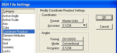
C.9. In the DGN File Settings dialog box under Category, choose Working Units. In the Modify Working Unit Settings area in the Unit Names group, in the Master Units: box, select Feet; in the Label: box enter ft; in the Sub Units: box, select Inches; and in the Label: box enter in.
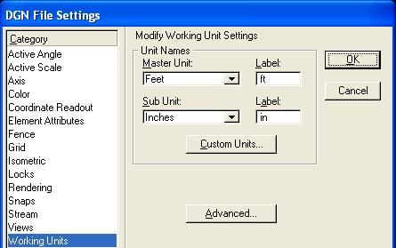
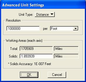
C.10. In the Modify Working Unit Settings area, press the Advanced... push button. An Alert box should open; press the OK push button. In the Advanced Unit Settings dialog box, set Unit Type to Distance, set Resolution to 1000000 per Foot, and press the OK push button.
C.11. In the DGN File Settings dialog box, press the OK push button.
C.12. From the MicroStation dialog box, choose Settings -> View Attributes.
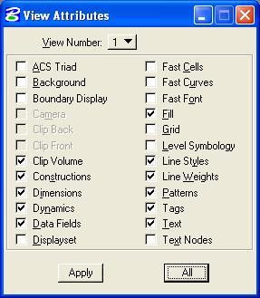
C.13. In the View Attributes dialog box, set ACS Triad to off, Background to off, Boundary Display to off, Clip Volume to on, Constructions to on, Dimensions to on, Dynamics to on, Data Fields to on, Displayset to off, Fast Cells to off, Fast Curves to off, Fast Font to off, Fill to on, Grid to off, Level Symbology to off, Line Styles to on, Line Weights to on, Patterns to on, Tags to on, Text to on, Text Nodes to off, press the All button, and close the View Attributes dialog box by pressing the "X" in the upper right corner of the dialog box.
C.14. From the MicroStation dialog box, choose Utilities -> Key-in.
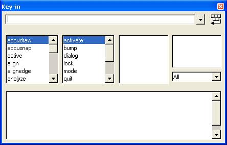
C.15. From the Key-in dialog box, minimize the Key-in dialog box by moving the mouse over the bottom edge of the Key-in dialog box until the up and down arrow appears, press and hold the left mouse button, move the mouse up until it is over the top edge of the Key-in dialog box, and release the left mouse button.

C.16. From the Key-in dialog box, dock the Key-in dialog box by moving the mouse over the words "Key-in" on the top edge of the Key-in dialog box, press and hold the left mouse button, drag the Key-in dialog box to the lower center part of the MicroStation dialog box, and release the left mouse button. This area will now be referred to as the key-in field.

C.17. From the MicroStation dialog box in the key-in field, enter "go=0" to set the global origin to zero and press the enter key.

C.18. From the MicroStation dialog box in the key-in field, enter "xy=0,0" and press the enter key.

Notice the "GO=0.0000,0.0000" message.
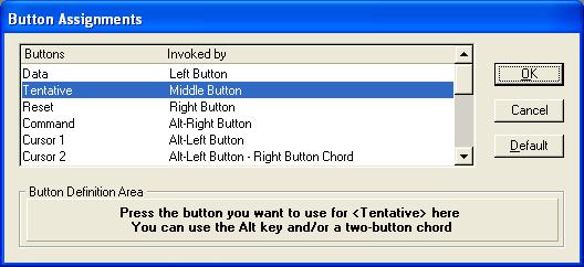
C.19. From the MicroStation dialog box, choose Workspace -> Button Assignments... In the Button Assignments dialog box under Buttons, choose Data. If the assignment under Invoked by is anything other than Left Button then move the mouse into the Button Definition Area and press the Left mouse button. In the Button Assignments dialog box under Buttons, choose Tentative. If the assignment under Invoked by is anything other than Middle Button then move the mouse into the Button Definition Area and press the Middle mouse button (the wheel). In the Button Assignments dialog box under Buttons, choose Reset. If the assignment under Invoked by is anything other than Right Button then move the mouse into the Button Definition Area and press the Right mouse button. Finally, press the OK button.
C.20. From the MicroStation dialog box, choose Window -> Views. If 2 has a check mark to the left of the number then press the number 2 to close view 2. Also close views 3-8 if open. 1 to 8 views may be on at any one time.

C.21. From the MicroStation View 1 dialog box in the upper right corner of the view, choose the middle icon to enlarge the view to the maximum size. The middle icon should look like the following image if it is at its maximum.

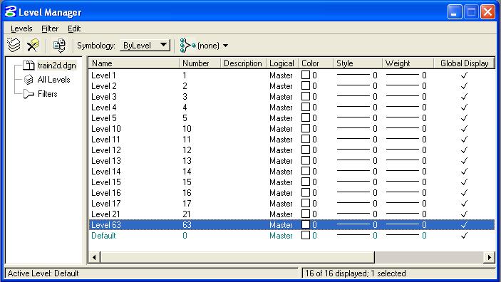
C.22. From the MicroStation dialog box, choose Settings -> Level -> Manager. In the Level Manager dialog box, choose Levels -> New and enter "Level 1" in place of "New Level(0)". Note in the column labeled "Number" that the level number is 1.


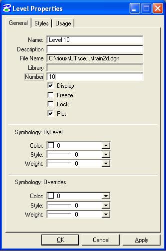
C.23. Repeat Step C.22 to add levels "Level 2", "Level 3", "Level 4", "Level 5", "Level 10", "Level 11", "Level 12", "Level 13", "Level 14", "Level 15", "Level 16", "Level 17", "Level 21", and "Level 63". To set the correct level number, in the Level Manager dialog box, select a level so that it is highlighted in blue, choose Levels -> Properties, enter the appropriate level number in the box to the right of Number, and press the OK push button. You may need to process the levels from highest to smallest number.
When completed, close the Level Manager dialog box by pressing the "X" in the upper right corner of the dialog box.
C.24. From the MicroStation dialog box, choose File -> Compress -> Design. This physically removes all logically deleted elements.
C.25. From the MicroStation dialog box, choose File -> Save Settings. This save all the design file settings so that when the file is open the next time, all the settings will be restored.
D. Save the design file as "lab_01.dgn".
D.1. From the MicroStation dialog box, choose File -> Save As...
D.2. In the Save As dialog box under Directories:, make sure your "x:\<first_character_of__username>\<_username>\microstation" directory is selected; then under Select Format To Save, select MicroStation V8 DGN Files [*.dgn]; then under Files:, enter "lab_01.dgn"; and finally press the OK push button.
D.3. The upper-left corner of the MicroStation dialog box should look like the following image.

E. Explore MicroStation.
E.1. The top of the MicroStation window has "File", "Edit", "Element", "Settings", "Tools", "Utilities", "Workspace", "Applications", "Window", and "Help" menus that provide the normal Windows functionality. See the above image. On some systems, "Applications" may not be displayed; please contact the instructor if this is the case.
E.2. The File menu contains the MicroStation specific items "Compress Design", "Save Settings", "Reference", "Print", "Exit", and others. Take this opportunity to look at the menus under File. Each time the user adds, deletes, or modifies an element with MicroStation, the change is immediately written to the design file.
E.2.a. File -> Compress Design is used to physically delete MicroStation elements that have been marked for deletion by the user from the current design file.
E.2.b. File -> Save Settings saves the current MicroStation settings in the current design file so that when the file is entered again, the same views, levels, etc. are restored.
E.2.c. File -> Reference allows the user to attach, detach, and manipulate reference files. Up to 256 reference files may be attached to a single design file for read-only access to the data. The reference files may be the current MicroStation design file, other MicroStation design files, or raster files. Each reference file may be displayed or not displayed and the levels to be displayed may be specified for each design reference file.
E.2.d. File -> Print allows the user to generate hard copy output of the design file.
E.2.e. File -> Exit terminates your MicroStation session.
E.3. The Edit menu contains the MicroStation specific items "Undo", "Redo", and numerous others. Take this opportunity to look at the menus under Edit.
E.3.1. Edit -> Undo allows the user to undo the last MicroStation command.
E.3.2. Edit -> Redo negates the last undo operation.
E.4. The Element menu contains the MicroStation specific items "Cells", "Dimensions", and several others. Take this opportunity to look at the menus under Element.
E.4.a. The Element -> Cells menu allows the user to attach and detach cell libraries (a file containing a collection of cells) and to select a cell for placement from among the cells in a cell library. A cell is a collection of one or more MicroStation elements that may be placed, manipulated, and deleted as one item. You may have only one cell library attached at any one time. Once a cell is placed, you no longer need the cell library attached because the cell is copied to the current design file. When shared cells are used, the definition of the cell is added to the design file only once at a location of (0,0), a scale of 1.0, and a rotation of 0.0 degrees and all other placements refer to the shared cell definition with specific location, scale, and rotation information. Shared cells thus use less disk space than normal cells. When normal cells are used, the cell is copied to the design file with specific location, scale, and rotation information applied when the copy is made.
E.4.b. The Element -> Dimensions menu provides for the selection of numerous attributed for dimensioning.
E.5. The Settings menu contains the MicroStation specific items "Design File...", "Level", "Locks", "Snaps", "View Attributes", and several others. Take this opportunity to look at the menus under Settings.
E.5.a. The Settings -> Design File menu allows the user to set or change many categories of items. We have used the Design File menu in section C above to set the Active Angle, Active Scale, Element Highlight Color, Drawing Pointer Color, Selection Set Color, Coordinate Readout, and Working Units.
E.5.b. The Settings -> Level menus allows the user to add and modify levels, to control which levels are displayed and hidden for each view (1-8 views may be on at any one time), and to control the active level (the level where all new user elements are placed). Level segregates the data by allowing the user to view or not view the data on individual levels. View levels can be applied to the single selected view, to multiple views, or to all views. The active level is indicated by the green color, the displayed level(s) are indicated by a black background, and hidden level(s) are indicated by tan backgrounds. The active level applies to all views. GEOPAK controls the level of each element placed by GEOPAK through the Design and Computation Manager. An organization can describe to GEOPAK the color, level, weight, and style for each GEOPAK object.
E.5.c. The Settings -> Level -> Manager menu allows the user to add and modify levels. Each level has a user-defined name, an assigned level number, an optional description, and other characteristics.
E.5.d. The Settings -> Level -> Display menu allows the user to control which levels are displayed and hidden for each view and to control the active level. View levels can be applied to the single selected view, to multiple views, or to all views. The active level is indicated by the green color, the displayed level(s) are indicated by a black background, and hidden level(s) are indicated by tan backgrounds.
E.5.e. The Settings -> Locks menu contains "Full", "Toggles", "Axis", "Grid", "Unit", "Association", "Level", "Graphic Group", "Text Node", and "Isometric". Toggles opens a dialog box to set "Axis Lock", "Grid Lock", "Unit Lock", "Snap Lock", "Association Lock", "Level Lock", "Graphic Group", "Text Node Lock", and "Isometric Lock". Full allows the user to specify additional parameters for some locks. Toggles allows the user to define whether the lock is active or not active. The locks controls how MicroStation uses tentative and data point buttons.
E.5.f. The Settings -> Snaps menu contains "Button Bar", "AccuSnap", "Nearest", "Keypoint", "Midpoint", "Center", "Origin", "Bisector", and "Intersection". The Button Bar creates a Snap Mode tool box which can be moved around the window or docked along any edge. The AccuSnap opens the AccuSnap Settings dialog box. The Nearest Snap uses the closest points on elements. The Keypoint Snap uses pre-defined keypoints on elements; the user can define the number of divisors for an element in the Settings -> Locks -> Full dialog box under Snap. The Midpoint Snap uses the midpoints of elements and segments of elements. The Center Snap uses the centers and centroids of elements. The Origin Snap uses the origins of cells. The Bisector Snap uses the midpoints of entire elements. The Snap Modes constrain an element to: Intersection - intersect another element with the point of intersection at its starting or ending point; Tangent - be tangent to another element; Tangent Point - be tangent to another element with the point of tangency at its starting or ending point; Perp - be perpendicular to another element; Perp Point - be perpendicular to another element with the point of intersection at its starting or ending point; Parallel - be parallel to another element; Point Through - pass through a particular point on the design plane; and Point On - start or end on another element.
E.5.g. The Settings -> View Attributes menu allows the user to control the viewing options for many items such as whether Construction elements are displayed or hidden, whether Fill is active or inactive (shapes are filled), whether the Grid is displayed or hidden, whether Line Styles are displayed, whether Line Weights are displayed, or whether Text is displayed. View Attributes can be applied to the single selected View Number using "Apply" or to "All" views.
E.6. The Tools menu contains the MicroStation specific items "Attributes", "Primary", "Standard", "Main", and numerous other tools. Take this opportunity to look at the menus under Tools.
E.6.a. If Tools -> Attributes does not have a check mark to its left then choose Attributes. The Attributes menu will appear. If the Attributes menu appears as below then dock the Attributes menu by moving the mouse over the words "Attributes" on the top edge of the Attributes menu, press and hold the left mouse button, drag the Attributes menu to the top of the MicroStation window to the leftmost position under File, and finally release the left mouse button. This action will dock the Attributes menu. The Attributes menu contains items for Active Level (Default in the picture below), Active Color (2 in the picture below), Active Line Style (3 in the picture below), Active Line Weight (thickness) (4 in the picture below), and a visualization of the line using the active color, style, and weight. Each MicroStation element may have specific values of each of these attributes based upon the current settings when the element is added to the design file. There are tools to allow the user to change any of the attribute values. MicroStation applications like GEOPAK may set the level, color, style, weight, and class of an element as they add an element to the design file without affecting the current settings.

E.6.a.1. Active Level specifies one level or drawing plane. Level segregates the data allowing the user to view or not view the data. Individual levels may be viewed or hidden at any time.
E.6.a.2. Active Color specifies one of 255 colors (0-254) from an active Color Table. The value in the Color Table specifies a 24-bit true-color value (16,777,216 color combinations) to be associated with the Active Color.
E.6.a.3. Active Line Style specifies one of 8 predefined numeric styles (0-7), one of 25 predefined named styles (Border to Wide Dash), or one of a virtually unlimited number of Custom styles. Line Style defines the appearance of data (solid, dashed, dotted, etc.). The user may create his/her own Custom styles (Element -> Line Style -> Custom).
E.6.a.4. Active Weight specifies one of 16 predefined weights (0-15). Weight defines the thickness or number of pixels displayed on the screen for graphics. When plotting the design file, the Weight can be converted to a line thickness.
E.6.b. If Tools -> Primary does not have a check mark to its left then choose Primary. The Primary Tools menu will appear. If the Primary Tools menu appears as below then dock the Primary Tools menu by moving the mouse over the words "Primary Tools" on the top edge of the Primary Tools menu, press and hold the left mouse button, drag the Primary Tools menu to the top of the MicroStation window to the left of the Attributes menu, and finally release the left mouse button. This action will dock the Primary Tools menu. The Primary Tools menu contains, from left to right, items for References (same as File -> Reference), Level Display (same as Settings -> Levels -> Display), Element Information; Toggle AccuDraw, and Pop Set Enable/Disable.

E.6.c. If Tools -> Standard does not have a check mark to its left then choose Standard. The Standard Tools menu will appear. If the Standard menu appears as below then dock the Standard menu by moving the mouse over the words "Standard" on the top edge of the Standard menu, press and hold the left mouse button, drag the Standard menu to the top of the MicroStation window to the left of the Primary Tools menu, and finally release the left mouse button. This action will dock the Standard menu. The Standard Tools menu contains, from left to right, items New, Open, Save, Print, Cut, Copy, Paste, Undo, Redo, MicroStation on the Web, and Help.

When the Attributes, Primary Tools, and Standard menus are docked, they should look like the following:

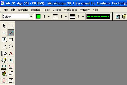
E.6.d. If Tools -> Main -> Main does not have a check mark to its left then choose Main. The Main Tools menu will appear. If the Main menu appears as below then dock the Main menu by moving the mouse over the words "Main" on the top edge of the Main menu, press and hold the left mouse button, drag the Main menu to the left edge of the MicroStation window, and finally release the left mouse button. The Main menu contains the MicroStation commands to add, modify, and delete elements and are (from left to right then top to bottom): the Element Selection tool, Fence commands, Points commands, Linear Elements (Lines) commands, Patterns commands, Polygons (Shapes) commands, Arcs commands, Ellipses (Circle) commands, Tags commands, Text commands, Groups commands, Cells commands, Measure commands, Dimension commands, Change Attributes commands, Manipulate commands, Delete Element command, and Modify commands. The icon for the most recently used command within a group is displayed. The background color for the active command is dark grey.

E.6.d.1. When the Main menu is docked, it should look like the following:
E.6.d.2. All the Main menu commands except the Delete Element command can be expanded to show all available commands in the group by moving the mouse over the Main menu command, press and hold the left mouse button, move the mouse horizontally over the desired command, and finally release the left mouse button. The name of the command will dynamically appear in the message box at the bottom of the MicroStation window as the mouse moves over a command.
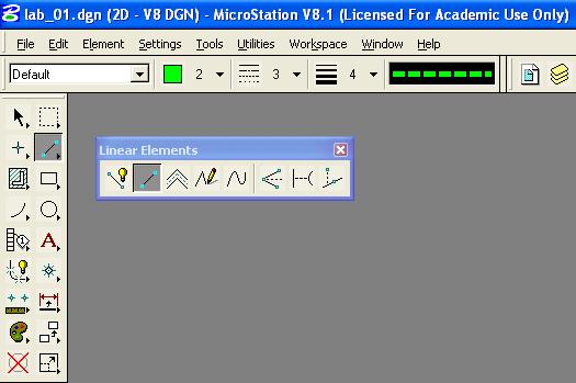
E.6.d.3. All the Main menu commands except the Delete Element command can be undocked to show all available commands in the group by moving the mouse over the Main menu command, press and hold the left mouse button, move the mouse horizontally then outside of the expanded command menu, and finally release the left mouse button. The command menu may be docked if desired. The following is the Linear Elements menu undocked.
E.7. The Utilities menu contains the MicroStation specific items "Key-in", "Install Fonts...", "MDL Applications", and several others. Take this opportunity to look at the menus under Utilities.
E.7.a. The Utilities -> Key-in dialog box allows the user to enter a MicroStation command, to select a MicroStation command from the hierarchical list of commands, or to select a MicroStation command from the list of recent key-in commands. In the key-in field, you may enter up-arrow and down-arrow keys for command recall and selection and enter the home, end, delete, backspace, left-arrow, and right-arrow keys for command editing. To paste text into the key-in field from the Windows paste buffer, move the cursor to the key-in field, press and hold the shift key, and press the insert key.
E.7.b. The Utilities -> Install Fonts dialog box allows the user to install user-defined fonts.
E.7.c. The Utilities -> MDL Applications dialog box allows the user to load (start), unload (stop), and get additional information about MDL Applications. GEOPAK is an MDL Application. Select Utilities -> MDL Applications. In the MDL dialog box in the Available Applications group, select FONTEDIT from the list and then press the Load push button. In the Open Font Library dialog box under Directories:, select the device and directory for MicroStation (normally "c:\Bentley") and select directory "Workspace\system\symb", then under Files:, choose font.rsc, and finally press the OK push button. In the character mapping dialog box in the Font group, choose 3 - Engineering and choose Display -> Screen Font. Press the Done push button. Finally, press the "X" in the upper-right corner of the MDL dialog box.
E.8. The Workspace menu contains the MicroStation specific items "Configuration...", "Button Assignments...", and several other items. Take this opportunity to look at the menus under Workspace.
E.8.a. The Configuration dialog box allows the user to specify many MicroStation parameters. Many of these configuration variables are set when you start MicroStation.
E.8.b. The Button Assignments dialog box allows the user to specify the association between the buttons on the mouse and the meaning to MicroStation. The Data button specifies a coordinate to MicroStation (or if the Tentative button was last used then accepts the snapped, calculated coordinate) and is normally the left button on the mouse. The Tentative button specifies a coordinate to MicroStation that causes MicroStation to search the design file for an element close to the coordinate specified, calculate a coordinate based upon the current snap feature, move an enlarged cursor to the calculated coordinate, and highlight the selected element. If the snapped, calculated coordinate is not acceptable, the user may enter additional Tentative buttons until an acceptable coordinate is displayed. To accept the Tentative button snapped, calculated coordinate, the user would enter a single Data button (the location of the cursor for the Data button is not pertinent). The Tentative button is normally the center button on a three-button mouse while the Tentative button is normally a left button - right button chord (left and right button pressed at the same time) on a two-button mouse. The Reset button specifies a reset or reject action to MicroStation and is normally the right button on the mouse. The definition of the Command button is not important because MicroStation interprets any button on a dialog box to be a Command button. If the buttons are not assigned the way that you want them, select a button from the list and in the Button Definition Area, press the mouse button or combination of Alt keys and mouse buttons that you want. When completed, press the OK push button.
E.9. The Applications menu contains menus added by MicroStation MDL Applications and MBE Applications. On some systems, "Applications" may not be displayed. GEOPAK and GEOPAK ROAD may be listed on the Applications menu. Take this opportunity to look at the menus under Applications.
E.10. The Window menu contains the MicroStation specific items "Views" and several others. Take this opportunity to look at the menus under Window. MicroStation can have up to 8 windows or views open simultaneously. Each window or view has its own size (height and width), location within the MicroStation window, levels to display or hide (Settings -> Levels -> Display), view attributes (Settings -> View Attributes), panning, zooming, rotation, and orientation (for 3D files: top, bottom, left, orthogonal, etc.). Choose Window -> Views; if 1 (for view 1) does not have a check mark to its left then select 1 (view 1 will be Opened) and if any of 2 through 8 has a check mark to its left then select each one (the view will be Closed).
E.11. The Help menu contains the MicroStation specific items to assist the user in using and finding online information about MicroStation. Take this opportunity to look at the menus under Help.
E.12. Each MicroStation View has a bar across the top border, a slider along the right border, and a bar and slider along the bottom border. Take this opportunity to look at the borders for Window 1.
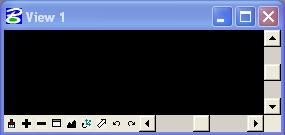
E.12.a. The bar across the top border of a MicroStation view contains the
view name on the left and three icons on the right. The
three icons are, from left to right, the Collapse icon, the Size icon (a
one-window icon  means the
MicroStation
view will be enlarged to fit the MicroStation window whereas a two-window icon
 means the MicroStation view
will be reduced to its previous size), and the Close icon. When the
MicroStation view is displaying the one-window Size icon, the
MicroStation
view may be moved or re-sized. Pressing and holding the left mouse
button on the top bar and then moving the mouse will cause the view to be moved
within the MicroStation window. Pressing and holding the left mouse button
on any of the four corners of the MicroStation view will re-size both the
horizontal and vertical dimensions of the MicroStation view.
Pressing and holding the left mouse button on any of the four edges of the
MicroStation
view will re-size either the horizontal and vertical dimensions of the
MicroStation view.
E.12.b. The slider along the right border of a MicroStation view allows the user to pan the design file in the vertical direction using either the up arrow, slider button, or the down arrow. The bar along the right edge of a MicroStation view applies only to the single MicroStation view.
E.12.c. The bar and slider along the bottom border contains, from left to right, the Update View icon (a paint brush) (paint or re-draw), the Zoom In icon (a "+" sign) (increase magnification), the Zoom Out icon (a "-" sign) (decrease magnification), the Window Area icon (zoom in by rectangle), the Fit View icon (view all elements), the Rotate View icon, the Pan View icon, the View Previous icon, the View Next icon, the left arrow, the slider button, and the right arrow. The bar along the bottom edge of a MicroStation view applies only to the single MicroStation view.
E.13. The message fields within the MicroStation dialog box are located at the bottom of the MicroStation dialog box on the left side. The field with "Match Element Attributes > Accept/Reject" normally contains the MicroStation command name ("Match Element Attributes") and the prompt ("Accept/Reject") for the next action to take for the command. The field with "Type=Line, Level=Default" normally contains MicroStation status information.

The Active Snap Mode button
 gives the user
quick access to the Snaps menu. The Active Locks button
 gives the user quick
access to the Locks menu. The Active Level button
 gives the user quick
access to the Active Level menu.
F. Exit MicroStation.
F.1. Choose MicroStation File -> Compress -> Design.
E.2. Choose MicroStation File -> Save Settings.
F.3. Choose MicroStation File -> Exit.
Lab Assignment 01 is due . No grade will be given for Lab Assignment 01.
Latest Update: 14 Jan 2008 09:16 PM